
Recommandé
Contenu connexe
Tendances
Tendances (20)
En vedette
En vedette (17)
Similaire à Gp 2012 part 2
Similaire à Gp 2012 part 2 (20)
Plus de VJTI Production
Plus de VJTI Production (20)
Dernier
Dernier (20)
Gp 2012 part 2
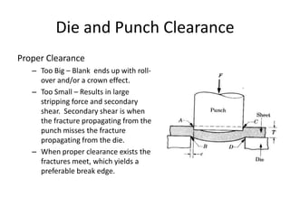
- 1. Die and Punch Clearance Proper Clearance – Too Big – Blank ends up with roll- over and/or a crown effect. – Too Small – Results in large stripping force and secondary shear. Secondary shear is when the fracture propagating from the punch misses the fracture propagating from the die. – When proper clearance exists the fractures meet, which yields a preferable break edge.
- 2. Forces for Cutting For Cutting: • In general ferrous stamping materials, shear strength is 70-80% ultimate tensile strength • Force=Shear Strength*Perimeter of Cut*Thickness • When calculating tonnage required it is recommended that ultimate tensile strength be used instead of shear strength to compensate for die wear. Tonnage=(UTS*Perimeter*Thickness) • Take caution in using value of shear strength. Consideration must be made for prior operations that may affect the material properties. – Work Hardening – Annealing or Tempering – Other processes that affect the mechanical properties of the material
- 3. Shear angle for Punch and die
- 4. Work and Energy • In terms of metal cutting: Energy of cutting =average force*Penetration • Force: Since the force/displacement curve for cutting sheet metal is nearly rectangular use the maximum force prior to fracture as the average force
- 5. Cutting Operations • Blanking – Material removed is the work-piece • Piercing – Material removed is scrap • Lancing – No metal removed, bending and cutting • Cut-off/Parting- Separating parts or reducing scrap strip size • Notching – Removing material from the outer edges of the strip • Shaving – Removing the break edge • Trimming – Removing “Flash” from drawn parts
- 7. Lancing
- 9. Notching
- 17. Progressive Dies • Dies fed directly from steel coil • No need for blanking operation • Scrap get cut away as part gets formed • Restricted to simple parts
- 18. Tool Design • It is a specialized area of manufacturing engineering which comprises the analysis, planning, design, construction and application of tools, methods and procedures necessary to increase manufacturing productivity. • Work holding tools – Jigs and Fixtures • Cutting tools • Sheet metal dies • Forging dies • Extrusion dies • Welding and inspection fixtures • Injection molds
- 20. Drawing
- 27. Bending
- 31. Bending • FIGURE 7.15 (a) Bending terminology. The bend radius is measured to the inner surface of the bend. Note that the length of the bend is the width of the sheet. Also note that the bend angle and the bend radius (sharpness of the bend) are two different variables. (b) Relationship between the ratio of bend radius to sheet thickness and tensile reduction of area for various materials. Note that sheet metal with a reduction of area of about 50% can be bent and flattened over itself without crackling. Source: After J. Datsko and C. T. Yang.
- 32. Methods of Reducing or Eliminating Springback • FIGURE 7.21 Methods of reducing or eliminating springback in bending operations..
- 39. Bending force : Maximum bending force, P = KLSt2 W K – constant ranges from 0.33(wiping die) – 0.66(u-die)-1.32(V-die) S – yield stress L- length of the bend t- thickness of sheet For a V-die Max bending force, P = (UTS)LT 2 W UTS – Ultimate tensile strength
- 42. Beading : • The periphery if the sheet metal is bent into the cavity of a die Fig 16.24 (a) Bead forming with a single die (b) Bead forming with two dies,in a press brake
- 43. Dimpling : • First hole is punched and expanded into a flange • Flanges can be produced by piercing with shaped punch • When bend angle < 90 degrees as in fitting conical ends its called flanging
- 48. Shear Spinning
- 49. Explosive forming : • Explosive energy used s metal forming • Sheet-metal blank is clamped over a die • Assembly is immersed in a tank with water • Rapid conversion of explosive charge into gas generates a shock wave .the pressure of this wave is sufficient to form sheet metals