
Recommandé
Contenu connexe
Tendances
Tendances (20)
Similaire à B.Arch Dissertation Design in modules
Similaire à B.Arch Dissertation Design in modules (20)
Dernier
Dernier (20)
B.Arch Dissertation Design in modules
- 1. DEENBANDHU CHHOTU RAM UNIVERSITY OF SCIENCE & TECHNOLOGYMURTHAL (SONEPAT) Department of Architecture “Design in Modules: How modular designing Affects architecture” Dissertation Report submitted in partial fulfilment of the requirement for the degree of Bachelor of Architecture (B. ARCH). Rajat Dhawan 2K13-ARCH-13001006052 DECEMBER 2017
- 2. 1 CONTENTS CHAPTER 1 1.1 INTRODUCTION………………………………………………….........8 1.2 HISTORY AND ORIGIN………………………………………….........9 1.3 AIM…………………………………………………………………… 10 1.4 OBJECTIVES…………………………………………………………………10 1.5 NEED IDENTIFICATION……………………………………………..10 1.6 SCOPE………………………………………………………………….11 1.7 LIMITATIONS…………………………………………………………11 1.8 RESEARCH METHODOLOGY……………………………………….12 CHAPTER 2 LITERATURE REVIEW 2.0 MODULAR ARCHITECTURE 2.01 ARCHITECCTURAL STYLE…………………………………………13 2.02 MODULES & MODULARITY………………………………………..14 2.03 MODULAR PREFABRICATED BUILDINGS………………………15 2.1 MIXEDUSE 2.1.1 ORIGIN………………………………………………………………16 2.1.2 MIXEDUSE CONCEPT IN INDIA………………………………….16 2.1.3 FORM & STRUCTURES……………………………………………17 2.1.4 MAINTENANCE/UPGRADATION………………………………...19 2.1.5 ACTIVITY TYPES…………………………………………………..20 2.1.6 PARAMETERS………………………………………………………22
- 3. 2 CHAPTER 3 LIBRARY STUDY 3.1 HIGH -RISE BUILDINGS 3.1.1. SERVICE CORES…………………………………………………..23 3.1.1.1 Orientation…………………………………………………24 3.1.1.2 Window Opening…………………………………………..24 3.1.1.3 Balconies…………………………………………………...24 3.1.1.4 Transitional Spaces…………………………………………25 3.1.1.5 Walls………………………………………………………..25 3.1.1.6 Plan…………………………………………………………26 3.1.1.7 Work spaces………………………………………………...26 3.1.1.8 Relationship to the street……………………………………26 3.1.2. STRUCTURES……………………………………………………….27 3.1.2.1 Raft foundation……………………………………………...27 3.1.2.2 Pile Raft Foundation………………………………………...29 3.1.2.3 Shear Wall…………………………………………………..30 3.1.3. STAIRS………………………………………………………………31 3.1.4. LIFTS………………………………………………………………...32 3.1.5. FIRE FIGHTING………………………………………………………33 3.1.5.1 Fire Control…………………………………………………..33 3.1.5.2 Heat Sensitive Detection System…………………………….33 3.1.5.3 Smoke Sensitive Detection System………………………….34 3.1.5.4 Fire alarm system…………………………………………….34 3.1.5.5 Fixed Fire Fighting Installation……………………………...35 3.1.5.6 Means of Escape……………………………………………..36
- 4. 3 3.1.6. PARKING…………………………………………………………......36 3.1.6.1 Ramp Break over Angle……………………………………...37 3.1.6.2 Driveway Exits……………………………………………….37 3.1.6.3 Parking Lot Layout Considerations………………………….38 3.1.6.4 Inter Lock Module……………………………………………39 3.1.6.5 Comparing Angle Efficiencies……………………………….39 3.1.6.6 One-Way Aisles………………………………………………40 3.1.6.7 Multi Level Car Parking……………………………………...40 3.2. OFFICES………………………………………………………………..41 3.2.1. Workstation Layout……………………………………………42 3.2.2. Office Layout…………………………………………………..44 3.2.3. Office Planning…………………………………………………45 3.2.4. Circulation……………………………………………………...47 3.2.5. Reception areas and visitor control……………………………..48 3.2.6. Conference room………………………………………………..49 3.3 RESTURANTS…………………………………………………………….49 3.3.1. Interior and External lighting…………………………………..51 3.3.2. Air Handling Units (AHU)……………………………………..52 3.4 RETAIL…………………………………………………………………….52 3.4.1. Shops……………………………………………………………55 3.4.2 Food court……………………………………………………….56 CHAPTER 4 CASE STUDIES…………………………………………………………….57 CASE STUDY I…………………………………………………………….57 CASE STUDY II……………………………………………………………63 CASE STUDY III…………………………………………………………..67 CASE STUDY IV…………………………………………………………..71
- 6. 5 List of figures: Fig. 1.1 A product module Fig. 1.2 Modular rice mats (tatami) in Japanese architecture Fig. 1.3 The modulor of Le Corbusier Fig. 2.1 Modular units in a housing Fig. 2.2 On site installation of a building module units Fig. 3.1 Combination of different low and high rise structure Fig. 3.2 Two more high rise structure Fig. 3.3 Single midrise structure Fig. 3.4 Single high rise structure Fig. 3.5 Mixed use parameters Fig. 3.1 Service Cores Fig. 3.2 Double core Fig. 3.3 Transitional spaces Fig. 3.4 Relationship of influencing factors Fig. 3.5 Details of Raft foundation(working) Fig. 3.6 Details of Raft foundation(views) Fig. 3.7 Details of pile raft foundatio Fig. 3.8 Details of RC Shear wall (exploded) Fig. 3.9 Details of RC Shear wall (plan) Fig. 3.10 Details of RC Shear wall Fig. 3.11 Staircase Details Fig. 3.12 Panoramic lift Fig. 3.13 Signage for fire safety Fig. 3.14 Parking interlock module Fig. 3.15 Parking layout Fig. 3.16 Multi-Level Car Parking Fig. 3.21 Vast open plan Fig. 3.22 Cluster open plan Fig. 3.23 Closed plan Fig. 3.24 Workstation layout 1 Fig. 3.25 Workstation layout 2
- 7. 6 Fig. 3.26 Office layout Fig. 3.27 Reception and office standards Fig. 3.28 Conference rooms Fig. 3.31 Small restaurant Fig. 3.32 Sitting standard Fig. 3.33 Restaurant areas Fig. 3.41 Shalves standards Fig. 3.42 Retail standards Fig. 3.43 Circulation & counter Fig. 3.44 Retail standards Fig. 3.45 Food court Fig. 3.46 HABITAT 67 Aerial view Fig. 3.47 Plan Fig. 3.48 Site Plan Fig. 3.49 Unit plan Fig. 3.50 View of HABITAT 67 Fig. 3.51 Balcony diagram Fig. 3.52 Section Fig. 3.53 Isometric section Fig. 3.54 At the time of construction Fig. 3.55 Bird eye view of Queen Alai airport Fig. 3.56 Key plan Fig. 3.57 Section Fig. 3.58 Modular Terrace Fig. 3.59 Roof top view Fig. 3.60 Interior view Fig. 3.61 Housing towe Fig. 3.62 Ant view Fig. 3.63 Side view Fig. 3.64 Structural Framework Fig. 3.65 Modules Fig. 3.66 Modules in Tower Fig. 3.67 Exterior view of the stadium Fig. 3.68 Approach to the stadium
- 8. 7 Fig. 3.69 Sitting spaces in the stadium Fig. 3.70 Proposed view of the stadium Fig. 3.71 Location of the stadium
- 9. 8 CHAPTER 1 1.1 INTRODUCTION Design in modules (or modular design) is a design method that subdivides a system into smaller parts called modules or skids that can be independently created and then used in different systems. A modular system can be characterized by functional partitioning into discrete scalable, reusable modules; rigorous use of well-defined modular interfaces; and making use of industry values for interfaces. Fig.1.1 A product module Due to rapid urbanization, shortage of land and high rate of relocation to cities, does not allow to provide custom houses for each individuals or group of individuals. There is need to have maximum housing space in minimum time, cost and land usage. This led to high density housing, the initial approach towards modular design. The benefits of modular design are flexibility in design and reduction in costs. Examples of modular systems are modular buildings, solar panels, wind turbines and so on. Modular design combines the advantages of standardization with those of customization. Modular design is not to be restricted to just housing. It is much more capable of than designs of disaster houses, high/low density housing etc. Most commercial and institutional projects have repetitive units which can be designed forming modules at various levels of sizes, i.e. it can be a room or number of rooms which will be repeated. It’s just a matter of designing and using the modules in different patterns or systems to create multiple options for a design without actually designing from scratch.
- 10. 9 1.2 HISTORY AND ORIGIN In classical architecture, the diameter of a column was used as a basis for a number of modules. In Japanese architecture, room sizes were determined by combinations of rice mats which were 90x180cm. Fig. 1.2 Modular rice mats (tatami) in Japanese architecture Work of Matila Ghyka’s on the golden section was one of the sources of the modular, but his work, in general, was used by other architects, such as Le Corbusier’s rival Andre Lurcat. Fig. 1.3 The modulor of Le Corbusier Andre Lurcat proposed his own range of proportions related to the work of builders as much as to that of designers. Proportions and modules–thus became a central issue in the post-war French modernisation, as architects struggled to maintain their status amid changing procedures in building production.
- 11. 10 1.3 AIM The aim is to achieve various designs, while achieving low-cost for development, as well as, cost saving in design and construction through modular approach. Modularity is pushing out the productivity frontier in design creation. On the contrary, modularity may lead to excess cost due to over-design, inefficient performance, and too many common modules may result in loss of design identity. 1.4 OBJECTIVES To understand the fundamentals of modularity w.r.t. architecture. To study the advantages/ limitations of modular design over conventional methods of design and construction, To study the scope of modular design at all the levels, i.e. design, construction, maintenance, upgradation. To analyze the different trends in modular design. To study its feasibility in Indian context and its use in current and future scenario. 1.5 NEED IDENTIFICATION Rapid economic growth has led to high rate of development. With the increasing value there is a need for radical reformation of construction industry to it more efficient in various sides. The prefabrication does allow quick construction with optimal quality but requires skills in production, transport and of components. Factory construction would help save a lot of time as the design be fed computers and the machines, robots can automatically generate full scale module ready for use. Modular designs are already in use in areas hit by natural disasters, for slum recuperation, inhabitable spaces like Antarctic, mountains, deserts, etc. though there is to see in normal conditions where people have the option to build as they want to. This is going to change as more and more urbanization takes place and there is lack of resources. Modular design is restricted to only a few building typologies. There has to be a way to apply modulation in a certain way hence breaking the boredom of a stack as in case of high rises. Also the buildings can be made such that modules can be added/ subtracted while in use without affecting the users.
- 12. 11 1.6 SCOPE The approach towards modular design might vary in case of architecture and other fields (software, product design etc.), but the basic theory, need for designing in modules, pros and cons are much similar. Object-oriented programming in software design, production/ assembly line in industrial/product design are very successful cases of design in modules. Prefabricated buildings still has to attain that level of popularity. The quick and cost efficient mode of construction will require the study of modular design in various types of existing projects which are mainly residential buildings like houses, housing, disaster mitigation, slum rehabilitation, etc. It shall not be restricted on economic basis as modular design can be of much importance to multi-use skyscrapers. So, there will be a study of its use in other typologies like commercial, institutional, industrial buildings. There has to be an analysis of forming modules at different scales. For example, an apartment in housing, floor in a skyscraper, a room in a house, etc. As a whole, the scope of this dissertation would be various building typologies like residential, commercial, institutional and industrial buildings with modular components with a minimum size of a room. 1.7 LIMITATIONS The study is restricted to modular design of buildings and does not apply to other designs of smaller scales and modular designs in other fields (software etc.). Modular design is not a popular concept in India, so the case studies done would be international and will rely on information in books and internet. Also, it is not possible to have technical construction details for the components in case studies. 1.8 RESEARCH METHODOLOGY STUDY AREAS AND ITS APPROACH The research is being done from many research papers, magazines,internet, thesis & dissertations, Time savers, and codes of india.The main approach of research is to comes up to the design strategies and solutions in applying the modular systems in various activities of an integrated building for e.g. it is either residential, commercial, retail, shopping complex etc. Most of the research also carried out through the case studies of those buildings which already carrying the concept of modularity or already are built in modules.The case studies, both conceptual and practical, are being done in India and outside of India (internet study).With the help of the Indian standards the study of particular spaces are done of a particualr bulding type for example the standards of offices, shops, housing units etc. are being studied.Also the parking standards and site standards are being done.
- 13. 12 The study tries to have a systematic approach of applying the modular systems in same or various types of spaces in any building and to upcoming with the probelems of cost effectiveness, space consumption, environment friendly etc. and how in modern time modular designing can overcome these problems. Today modular designing is used in many part of countries in every aspect and type of buildings. It helps in reducing the cost of construction as the mostly construction is been done in the factories and only the installation work is done on site. Rather than using this concept in commercial or other activities it is majorly use in making the residential apartments either lowrise , midrise or highrise. Modularity creates value but its not free .There are the costs of making an interdependent system modular. The process of modularizing a complex system is generally a lengthy, pain-stacking for every important design dependency must be understood and addressed via a design rule. Research methodology chart
- 14. 13 CHAPTER 2 LITERATURE REVIEW 2. MODULAR ARCHITECTURE 2.1 ARCHITCETURE STYLE Architecture can be categorize in many ways where modular is also a style of architecture. Practically fully modular architecture very much rare and almost all architecture styles are in somewhere between them.On one hand, modular architecture has functionally de-coupled interfaces between components. In practice, this often leads to architecture that is one, where the functional elements in the building are mapped one-to-one to the components of the design. However, an integral architecture is the opposite of modular architecture. Integral architecture has coupled interfaces between components. It tends to have more complex (not one-to-one) mapping from functional elements in the function structure to the components of the design. 2.2 MODULES & MODULARITY A separable component, frequently one that is interchangeable with others, for assembly into units of different sizes, complexity or function.Modularity means using the same module in multiple configurations enabling a large variety of designs without using many component types. This modularity brings several advantages such as reduced capital requirements and economies. Modularity is especially advantageous when the scale and scope of the project are relatively large. In such cases, it is a practical and economic option. Modular architecture is also a component based system in which components are assembled to make the entire building. When a design is "modularized" the elements of the design are split up and assigned to modules according to a recognized architecture or plane Modular design is an attempt to combine the advantages of standardization (high volume implies low manufacturing costs) with those of customization. Modularity can be characterized by: • Functional separating into reusable modules consisting of isolated, self- contained functional elements - Dividing the project in discrete modules of appropriate scale with specific function dedicated to each of them.
- 15. 14 Fig. 2.1 Modular units in a housing • Laborious use in the different modular interfaces - There can be many cases in which the modules designed can be used apart from the particular purpose for they were designed. • In case of a correction/ change only the desired module will be interrupted as it will not be directly related to any of the other modules • Use of industry standards for key interfaces — the modules formed might be standardized so that they can be used in future projects with/ without any change Even though it makes the process easier, it limits the creativity. In general, modularization serves three purposes, any of which may justify an investment in modularity: • Modularity makes complexity practicable - Dividing the project into a number of smaller units which are easier to handle. •Modularity enables parallel work - The work can be divided so no individual gets the burden of everything. •Modularity is tolerant of improbability - Particular elements of a modular design may be changed after the fact and in unforeseen ways as long as the design rules are obeyed. The process of modularizing a complex system is generally a lengthy, pain-staking process. For every important design dependency must be understood. There has to be rules set before to design a module so that it can attach with other modules and is self-sustainable if some of the adjacent modules are removed/changed. So the modules thus generated are independent as well as inter-dependent.
- 16. 15 2.4 MODULAR PREFABRICATED BUILDINGS Modular buildings and modular homes are a type of sectional prefabricated buildings, or houses, that consist of multiple sections called modules. "Modular" is a method of construction different from other methods of building. The module sections are constructed at an off-site facility, then delivered to the offered site of use. Complete construction of the prefabricated sections are completed on site. The prefabricated sections are sometimes lifted and placed on basement walls using a crane, the module prefabricated sections are set onto the building's foundation and joined together to make a single building. The modules can be placed side-by-side, end-to-end, or stacked, allowing a wide variety of configurations and styles in the building layout. Fig. 2.2 On site installation of a building module units
- 17. 16 2.1 MIXEDUSE 2.1.1 ORIGIN Mixed use is one of the ten principles of smart Growth , a design strategy that seeks to short- term community design and development that serves the economy, community, public health, and the environment. The term may also be used more specifically to refer to a mixed-use real estate development project a building, complex of buildings, or district of a town or city that is developed for mixed-use by a private developer, governmental agency, or a combination thereof. Traditionally, human settlements have developed in mixed-use patterns. However, with industrialization as well as the invention of the skyscraper, governmental zoning regulations were introduced to separate different functions, such as manufacturing, from residential areas. 2.1.2 MIXEDUSE CONCEPT IN INDIA Mixed land use projects tend to give better revenues as against standalone projects. Depending on the size and location, a developer has to take numerous approvals from various regulatory bodies, which results in delays and hits timely delivery of projects. Also, there are chances of unruly developments on mixed use area, so the distribution of different types of land within each zone should specify appropriate division to avoid such lawless developments. The only danger is that once an area is identified for mixed use, the risk of ungovernable development increases, which defeats the purpose of planned mixed use. To avoid such a scenario it is important to have sections to specify the percentage distribution of different types of land uses. Many state governments have laws which require the percentage of area for residential projects and the percentage for commercial activity; but these laws do not oversee the kind of shops that will come up there. Since the movement of opting for residences in the outskirts has started, it is also our responsibility to see to it that the basic amenities are made approachable to customers. In our projects, we have maintained that people get good shopping destinations that gel with their lifestyle. Instead of putting many shops, we prefer to place a select few of repute. Developers have realized the potential of such places and that is a reason the Delhi NCR is busy with such projects. The potential of mixed use development in certain areas of the NCR like Noida-Greater Noida Expressway, NH 24, etc., is very good. As people are increasingly moving to these areas, the attention of people will increase exponentially once good mixed use developments are developed.
- 18. 17 There is a provision for mixed land use only in Yamuna Authority. Yamuna Authority is allotting mixed land use plots in SDZ (Special Development Zone) for core activities like service sector, commercial, residential, industrial, etc. For Noida and Greater Noida, we are planning to launch mixed land use plots for various activities. Though, in the initial stages, it may look that these mixed use developments take time to develop, in the medium and long-term, these townships develop faster since they have options of healthcare, retail, commercial, residential and educational institutions. 2.1.3 FORM & STRUCTURE Mixed land use development can take four general forms:- 1. It can be a combination of different low and high rise structures on a single site with retail on ground level with residential units above in one structure and office space above one in another structure. Fig. 3.1 Combination of different low and high rise structure
- 19. 18 2. It can be two or more high rise structures on a single site with each structure holding a different use which includes office building, residential towers and hotel. Fig. 3.2 Two more high rise structure 3. It can be a single midrise structure on a single site typically in an urban setting with retail on ground, then residents on above floor and office area is laid upon them. Fig. 3.3 Single midrise structure 4. It can be a single high rise structure on single site that contains two or more uses integrated into the structure in which retail on street level with offices above them and either residential units or hotel spaces over the office spaces.
- 20. 19 Fig. 3.4 Single high rise structure 2.1.4 MAINTENANCE/UPGRADATION • No interdependence among spaces. • What are the factors affecting the expansion/extension of the building? • Can it be used to design spaces which may change its usage after a period of time? Finally, there will be case studies which would help in understanding the theory and its practical applications in different contexts and variety of solutions. 2.1.5 ACTIVITY TYPES Residential Apartments Office Suites Studio Apartments Luxury Hotels Commercial-Retail shopping brands
- 21. 20 Exhibition and Art Gallery Multiplex Observing floors in the top of iconic tower Parking 2.1.5 IMPACTS o Environment impact of Mixed use • Indorsing multiplicity of land use could put an extra burden on infrastructure. • Redefining the built environment. • Cities can be made more compact reducing the need of long distance travels • Housing large number of peoples in few buildings can create well-knit and close communities. • Use of mass public transportation and minimizing the use of personal vehicles. o Social impact of Mixed use • People will get good quality of life in totality including travelling, education, shopping and entertainment. • Compact neighbourhoods • Mixing land uses yields socio-economic benefits and therefore has a positive effect on housing values. • Activating the declined zones through mixing the residential uses, public institutions and commercial activities
- 22. 21 o Economic impact of Mixed use * Construction of mixeduse building is expected to cost in millions, general of residential, commercial and parking portions. *This activity will generate additional jobs and activity in the surrounding region. * Some impacts, mainly related to the construction of the building, are obvious and relatively easy to quantify. Other impacts related to the economic activity of residentials and commercial tenants is difficult to predict because those predictions depend on on future factors that cannot be foreseen. 2.1.6 PARAMETERS As mixed use development offering Residents, Serviced Apartments, Hotels, Shopping Mall, Office Spaces and Recreational spaces. Mixed use development and its benefits redefine this project as an Epicentre. Fig. 3.5 Mixed use parameters
- 23. 22 Some parameters of mixed use development: - To promotes active transport between different activities by locating origins and destinations close to each other and reduces transportation cost(fuel cost). - To encourage social interaction between different groups of peoples. - To include a range of employment, education, recreation and retail transport. - To achieve TRANSIT ORIENTED DEVELOPMENT (T.O.D.)
- 24. 23 CHAPTER 3 LIBRARY STUDY AND CASE STUDY 3.1 HIGH RISE BUILDING 3.1.1 SERVICE CORES Service core position is of central importance in the design of the tall building. The service core not only has structural ramifications, it also affects the thermal performance of the building and its views, and it determines which parts of the peripheral walls will become openings and which parts will comprise external walls. CENTRAL CORE DOUBLE CORE SINGLED-SIDE CORE Fig. 3.1 Service Cores DOUBLE CORE HAS MANY BENEFIT In the tropics, cores should preferably be located on the hot east and west-sides of the building. Studies have shown that minimum air- conditioning loads result from using the double-core configuration in which the window openings run north and south, and thecores are placed on the east and west sides. The same considerations apply in temperate zones. Fig. 3.2 Double core
- 25. 24 3.1.1.1 Orientation Tall buildings are exposed to the full impact of external temperatures and radiant heat. Accordingly, the overall building orientation has an important bearing on energy conservation. In temperate zone openings facing north and south gives the greatest advantages in reducing insulation (and the resulting air-conditioning load). It frequently happens that the geometry of the site does not coincide with sun path geometry. In these cases, the other built elements may, if expedient for planning purposes, follow the site geometry. Typical floor window openings should generally face the direction of least insulation (north and south in the tropics).Corner-shading adjustments or shaping may need to be done for sites further north or south of the tropics or for non-conformity of the building plan to the solar path. 3.1.1.2. Window Opening Generally, window openings should orientate north and south unless important views require other orientations. If required for aesthetic reasons, curtain walling may be used on non-solar facing facades. On other faces of the building some form of solar shading is required, while the quality of light entering spaces should also be transitional spaces can have adjustable glazing at the other face so that balconies or recesses can act as 'sun spaces', collecting solar heat, like a greenhouse or conservatory. 3.1.1.3. Balconies Deep recesses may provide shade on the building's hot sides. A window can be totally recessed to form a balcony or a small sky court that can serve a number of functions besides shading. Placing balconies on hot elevations permits glazing to these areas to be full-height clear panels. These can give access to the balcony spaces which can serve as evacuation spaces, as large terraces for planting and landscaping, and as flexible zones for the addition of future facilities. 3.1.1.4. Transitional Spaces Large multi-storey transitional spaces might be introduced in the central and peripheral parts of the building as air spaces and atriums. These serve as 'in-between' zones located between
- 26. 25 the interior and the exterior. They should function like the verandah ways of the old shop houses or the porches of early nineteenth-century masonry houses of the tropics. Atriums should not be totally enclosed but should be placed in this in-between space. Their tops could be shielded by a louvered roof to encourage wind-flow through the inner areas of the building. These may also be designed to function as wind scoops to control natural ventilation to the inner parts of the building. NORTH SOUTH ORIENTATION RECESSES MULTI-STOREYTRANSITIONAL SPACES Fig. 3.3 Transitional Spaces 3.1.1.5. Walls External walls should be regarded as permeable, environmentally interactive membranes with adjustable openings (rather than as a sealed skin). In temperate climates the external wall has to serve very cold winters and hot summers. In this case, the external wall should be filter-like, with variable parts that provide good insulation but are open able in warm periods. In the tropics the external wall should have moveable parts that control and enable good cross-ventilation for internal comfort, provide solar protection, regulate wind-driven rain, besides facilitating rapid discharge of heavy rainfall. 3.1.1.6. Plan The building plan, in addition to responding to the commercial intentions of the building should reflect the patterns of life and culture of the place, and its climate. In part this involves an understanding of the spatial modalities of the people, the way they work, the way culture
- 27. 26 arranges privacy and community. The plan should also reflect air movement through the spaces and the provision of sunlight into the building. 3.1.1.7. Work spaces Work spaces, even in a high-rise commercial development, have to have some degree of humanity, some degree of interest and some use of scale. For example, large sky courts and terraces might function as communal spaces as well as means of ventilation for the upper parts of the building. 3.1.1.8. Relationship to the Street The ground floor in the tropics should preferably be open to the outside and naturally ventilated. The relationship of the ground floor to the street is also important. The introduction of the indoor atrium at the ground floor may mean the demise of street life. Freestanding fortress-like buildings also tend to separate the building from the pavement, further alienating the street. Planting and landscaping should be used not only for their ecological and aesthetic benefits, but also to cool buildings. Planting should be introduced as vertical landscaping to faces and inner courts of upper parts of tall buildings. Plants absorb carbon dioxide and generate oxygen, benefiting the building and its surroundings. Relationship to the street: – Open-to-sky Ground Floor Vertical Landscaping Fig. 3.4 Relationship of influencing factors
- 28. 27 3.1.2. STRUCTURES 3.1.2.1. Raft foundation Raft foundations are used to spread the load from a structure over a large area, normally the entire area of the structure. They are used when column loads or other structural loads are close together and individual pad foundations would interact. Fig. 3.5 Details of Raft foundation A raft foundation normally consists of a concrete slab which extends over the entire loaded area. It may be stiffened by ribs or beams incorporated into the foundation. Raft foundations have the advantage of reducing differential settlements as the concrete slab resists differential movements between loading positions. They are often needed on soft or loose soils with low bearing capacity as they can spread the loads over a larger area. Fig. 3.6 Details of Raft foundation
- 29. 28 Raft or mat foundation is a combined footing that covers the entire area beneath a structure and supports all walls columns. Raft foundation is generally suggested in the following situations: Whenever building loads are so heavy or the allowable pressure on soil so small that individual footing would cover more than floor area. Whenever soil contains compressible lenses or the soil is sufficiently erratic and it is difficult to define and assess the extent of each of the weak pockets or cavities and thus estimate the overall and differentia settlement When structures and equipment to be supported are very sensitive to differential settlement. Buildings where basements are to be provided or pits located below ground water table. Buildings where individual foundation ,if provided will be subjected to large widely varying bending moments which may results in differential rotation and differential settlement of individual footings causing distress in the building. 3.1.2.2. Pile Raft Foundation: A pile is a column of concrete either cast in or driven into the ground to transfer loads through the poor bearing soil to a more stable stratum. The piles support reinforced concrete beams off which load bearing wall are built. Fig. 3.7 Details of pile raft foundation
- 30. 29 •The soil near the surface doesn’t have sufficient bearing capacity (weak) to support the structural loads. • The estimated settlement of the soil exceeds tolerable limits • Differential settlement due to soil variability or non-uniform structural loads is excessive • Excavations to construct a shallow foundation on a firm soil are difficult or expensive. 3.1.2.3. Shear Wall Shears wall are Reinforced concrete walls used in buildings in addition to slabs, beams and columns as vertical support. Shears walls generally start at foundation level and are continuous throughout the building height. Their thickness can in ≤150mm to ≥ 400mm in high rise buildings. Shear walls are usually provided along both length and width of buildings. They are like vertically-oriented wide beams that carry earthquake loads downwards to the foundation. Fig. 3.8 Details of RC Shear wall Shear walls in buildings must be symmetrically located in plan to reduce ill-effects of twist in buildings. Shear walls are more effective when located along exterior perimeter of the building such a layout increases resistance of the building to twisting.
- 31. 30 Fig. 3.9 Details of RC Shear wall Shear walls are oblong in cross-section, i.e., one dimension of the cross-section is much larger than the other. While rectangular cross-section is common, L- and U-shaped sections are also used. Thin-walled hollow RC shafts round the elevator core of buildings also act as shear walls, and should be taken advantage of to resist earthquake forces. Fig. 3.10 Details of RC Shear wall Under the large overturning effects caused by horizontal earthquake forces, edges of shear walls experience high compressive and tensile stresses. To ensure that shear walls behave in a ductile way, concrete in the wall end regions must be reinforced in a special manner to sustain these load reversals without losing strength.
- 32. 31 3.1.3. STAIRS: Stairs governed by building regulations must have a width of 1m. Landing length =n times the length of tread + one depth of step. The time required for complete evacuation must be calculated for stair widths in office buildings. Every main staircase must be set in its own continuous stairwell, which together with its access routes and exit to open air, should be designed and arranged so as to ensure its safe use as an emergency exit. Fig. 3.11 Stairs Details 3.1.4. Lifts : The building and its function dictate the basic types of lift which need to be provided. They serve as means of vertical Transport for passengers and patients. While designing buildings one should be planned in such a way that even 10yrs lifts are capable of meeting the increase demand. Alternations to installations that have been badly or too-cheaply planned can be expensive or even completely impossible. During the planning stage the likely usage should be closely examined. Fig. 3.12 Panoramic lift An important requirement in providing an elevator service for a building is the location of the elevators (in one or more groups, depending on the size of the building) in relation to access from the entrances and also in relation to the layout of the upper floors. Since elevator shafts
- 33. 32 are normally vertical, their location on plan imposes a major constraint on every floor of the building. If the building is not of uniform height, at least one elevator group must be located in the tallest portion. The main criteria for the design of an elevator group can be Summarized under a few headings: •Capacity to handle the passengers as they arrive, with minimum queuing, expressed as a percentage of the total building population that can be handled in the peak 5-minute period. •Frequency to provide an available car for arriving passengers without excessive waiting, expressed as the average time interval between cars. •Car size to handle the largest items required to be carried, for example, an occasional item of furniture, or a hospital bed with attendant, or a group of hotel guests with their baggage. •Speed of total trip, so that passengers do not perceive the total service as excessively slow. Automatic, multi-functions lifts shall be provided for multi-story buildings. •A minimum of two passenger lifts with separate access, each 1,250 kg shall serve the office floors. •Lift engine room will be located above the top floor. •Lifts should be traction type, and not hydraulic if possible. Hydraulic is very slow and higher maintenance. •Buildings that are furnished with loading docks should evaluate installing a separate freight elevator to handle received materials. •Maintenance equipment access to the roof should be evaluated based campus.
- 34. 33 3.1.5. Fire Fighting: Fire is supported by three essential ingredients, fuel, heat and oxygen. The absence of any of these causes fire to be extinguished. The firefighting system must be appropriate to the location of the fire and preferably limited to the area in order to minimize damage to plants and building structure. Radiation from fire may prove combustion to combustible material at some distance. Firefighting implies the ability of building element to fulfill their assigned functions under condition if maximum severity of exposure to heat expected to occur in the building. It is a measure of: • Resistance to collapse • Resistance to flame penetration. • Resistance to excessive temperature rise on the unexposed face. 3.1.5.1. Fire Control Detection and alarm system: Smoke detectors Heat detectors Manual system Automatic alarm 3.1.5.2. Heat Sensitive Detection System Heat sensitive detection system provides automatic sprinklers, alarm and control. It is basically a nozzle with an orifice fitted with a flow control device and a deflector that will distribute water over a green area. When the bulb is heated, the liquid expands, absorbing the bubble of air and breaking the bulb, releasing the sprinkler cap. Sprinklers are designed to real ease at various temperatures ranging from 57degree C to 260 degree C. Maintenance of water pressure, Water from appropriate supply is fed to an automatically controlled pump and to main control valve of the system. Above this is the alarm valve, which is kept closed by the trapped pressure of water. When sprinkler operates this pressure falls and the valve opens and excess water flows up a vertical riser to a main distributor pipe at each ceiling.
- 35. 34 3.1.5.3. Smoke Sensitive Detection System • The system detects the fire with the help of smoke and then alarm automatically initiated control of fire is done manually. Detector to be sited at highest parts of enclosed area, so mounted that sensitive area is not less than 25mm or more then 600mm below the roof ceiling. • Inlet of each returns air ducts shall have a detector on its center, if continuous inlet detector at every room of its length. 3.1.5.4. Fire alarm system There are two types of fire alarms system: 1. Manual systems- Manual call point is manually operated device to initiate an alarm. They are made of sturdy M.S. enclosure and provided with a hammer to break the glass to initiate as alarm. 2. Automatic fire alarm system – These are connected to detectors which on sensing some exposure to heat or smoke direct the alarm system to initiate automatically. 3.1.5.5. Fixed Fire Fighting Installation Automatic sprinklers Automatic sprinklers protect high fire risk public and manufacturing buildings. These may be a statuary requirement if the building exceeds the volume of 7000 cum. Sprinkler water outlets are located at about 3m centers, usually at ceiling level and spray water in a circular pattern. A deflector plate directs the water jet over the hazard or onto walls or the structure. Each sprinkler has a frame containing a colored liquid for leak detection, which seals the water inlet. Upon local overheating the quartz expands the fractures, releasing the spray. Water flow is detected and starts an alarm, pressure boosting set and automatic link to the fire brigade monitoring station. Sprinklers should be installed in: •Basements used as car parks or storage occupancy, if the area exceeds 200 sq.m. •Multi-level basements, used as car parks and housing essential services ancillary to a particular occupancy or for storage occupancy, excluding any to be used for sub-station, A.C. plant and DG set.
- 36. 35 Fire escape staircase: These are stairs used for escaping during fire. They can be used for general public as vertical circulation or as service stairs otherwise in the building. According to NBC: •No space in an office building should be more than 30mts from the fire escape stairs. •Fire escape stairs could be either open to air or should have blower system to suck out air from the stairs area in case of fire. • All fire escapes should terminate in an open area or near the entrance in the ground floor. 3.1.5.6. Means Of Escape: The only sound basis for designing means of escape from first is to attempt to locate the position of all possible sources of outbreak of fire and to predict the courses which might thereafter be allowed by the fire as it develops. The main stairways were developed in smoke at the end of seven minutes. All corridors were impassable after 16 minutes. The emergency staircases remain passable due to self-closing fire doors. To remove smoke, fresh air should be introduced at each level. Fig. 3.13 Signage for fire safety
- 37. 36 A corridor 10m length that is filled with smoke cannot be used to get to an enclosed stairway. Tests show that removal of smoke as one of the most important fire protection problems. 3.1.6. PARKING 3.1.6. 1. Ramp Break Over Angle: The ramp break over angle is the measure of ability of the car to break over a steep ramp, either climbing or descending, without scraping. Angle of Departure: A reasonable minimum value is necessary to reduce the incidence of tailpipe and rear bumper dragging. The standard calls for a minimum of 10 degrees, violated only in the 1957-1959 period. Only one 1970 car, Mercury, met the minimum standard. Most cars are substantially above 10 degrees. The most critical condition is at driveways where the apron is steep, or a combination of excessive crown to gutter and apron slope. Angle of Approach The trend of approach angle of domestic cars from 1948 to 1962 indicates a drop in the 1957-1959 periods below 15 degrees. The standard developed in 1960 by the Society of Automotive Engineers calls for a minimum value of 15 degrees. Ramp Slopes The maximum ramp slope should be 20 percent. For slopes over 10 percent, a transition at least 8 ft. long should be provided at each end of the ramp at one half the slope of the ramp itself. 3.1.6. 2. Driveway Exits A ramped driveway exit rising up to a public sidewalk must have a transition section that is almost level (maximum slope: 5 percent) before intersecting the sidewalk to prevent the hood of the car from obscuring the driver's view of pedestrians on the walk. This transition should be 16 ft. long.
- 38. 37 Property line walls should also be regulated so as not to interfere with the driver's view of pedestrians on a public sidewalk. Wherever an exit driveway is parallel and adjacent to a property line wall which extends all the way of a sidewalk, the edge of the driveway should be physically established, by curb or railing, at least 6 ft from that wall. For each foot that the wall is held back from the sidewalk, the required distance between driveway and wall may be reduced by one foot. 3.1.6. 3. Parking Lot Layout Considerations: The objective of the layout design is to maximize the number of stalls, while following the guidelines below. •The layout of the parking facility must be flexible enough to adapt to future changes in vehicle dimensions. •The stall and aisle dimensions must be compatible with the type of operation planned for the facility. The critical dimensions are the width and length of stalls, the width of aisles, the angle of parking, and the radius of turns. All of these dimensions are related to the vehicle dimensions and performance characteristics. In recent years there have been a number of changes in vehicle dimensions. An impact on the design of parking facilities. For the near future, a wide mix of vehicle sizes should be anticipated. There are three approaches for handling the layout: 1. Design all spaces for large-size vehicles (about 6 feet wide and 17-18 ft long). 2. Design some of the spaces for large vehicles and some for small vehicles (these are about 5 ft. wide and 14-15 ft. long). 3. Provide a layout with intermediate dimensions (too small for large vehicles and too big for small vehicles). For design, it is customary to work with stalls and aisles in combinations called "modules". A complete module is one access aisle servicing a row of parking on each side of the aisle. The width of an aisle is usually 12 to 26 feet depending on the angle at which the parking stalls are oriented. Stall Width: For simplicity, the stall width is measured perpendicular to the vehicle, not parallel to the aisle. If the stall is placed at an angle of less than 90o , then the width parallel to the aisle will increase while the width perpendicular to the vehicle will remain the same. Stall Length: The length of the stall should be large enough to accommodate most of the vehicles. The length of the stall refers to the longitudinal dimension of the stall. When the stall is rotated an angle of less than 90o , the stall depth perpendicular to the aisle increases up to 1 foot or more. It should be noted that the effective stall depth depends on the boundary conditions of the module, which could include walls on each side of the module, curbs with or
- 39. 38 For parking at angles of less than 90o , front bumper overhangs beyond the curbing are generally reduced with decreasing angle and, for example, drop to about 2 feet at 45o angles. Fig. 3.14 Parking lot layouts 3.1.6. 4. Inter Lock Module A special type of module, the interlock, is possible at angles below 90o . There are two types of interlock. The most common, and preferable, type is the bumper-to-bumper arrangement. The second type, the "herringbone" interlock, can be used at 45o and is produced by adjacent sides having one way movements in the same direction. This arrangement requires the bumper of one car to face the fender of another car. Figure 8-3 shows several different module layouts that are commonly used. Fig. 3.14 Parking interlock module
- 40. 39 Fig. 3.15 parking layout 3.1.6. 5. Comparing Angle Efficiencies : The relative efficiencies of various parking angles can be compared by looking at the number of square feet required per car space (including the prorated area of the access aisle and entrances). Where the size and shape of the tract is appropriate, both the 90o and the 60o parking layouts tend to require the smallest area per car space. In typical lot layouts for large size vehicles, the average overall area required (including cross aisles and entrances) ranges between 310 and 330 square feet/car. A very flat angle layout is significantly less efficient than other angles.
- 41. 40 3.1.6. 6. One-Way Aisles There are many conditions where one-way aisles are desirable. With parking angles less than 90o , drivers can be restricted to certain directions. However, the angle should usually be no greater than 75o . Drivers may be tempted to enter the parking aisles and stalls from the wrong direction when the stall angle is too large. 3.1.6. 7. Multi-Level Car Parking : Car sales, close to 8 lakhs units a year, are growing at an average rate of 10 per cent while two- wheeler sales at 5 million are expected to grow 14-15 per cent. In order to accommodate the large volume of vehicles, small cities and towns must develop their infrastructure - roads, flyovers, car parks and other facilities. Otherwise their arteries are most likely to get clogged like they do in big and mini metros. Fig. 3.16 Multi-Level Car Parking One solution may be a multi-level car parking system to maximize car parking capacity by utilizing vertical space, rather than expand horizontally. Although at a nascent stage in India, it is one of the options to decongest roads and solve parking problems.
- 42. 41 3.2. OFFICES : The idea that the working environment should be enjoyed, rather than suffered is becoming more important recently, because most works are professionals or managers with a very hectic schedule. Today's corporate clients demand new offices & facilities with designs focused not only on the building appearance but also on critical workspace issues. Different workspace options are discussed here: 1. THE VAST OPEN PLAN Advantages of centre core: -It allows all window space to be utilized as rentable office space. Central location permits offices of varying depths to receive natural light. The central location is also extremely convenient in terms of access and in some cases may be equidistant for all sides. This simplifies area division and provides good flexibility of tenant distribution. Disadvantage:-The central interior location limits the depth of offices in the mid zone of each floor, thus affecting the element of flexibility in office layout. Central core requires an access corridor around its perimeter hence results consuming floor area. Fig. 3.21 Vast open plan 2. CLUSTER OPEN PLAN Advantages: - The off-centre interior core permits all window or building perimeter space to be used for offices. However, it presents somewhat more flexibility in maximum depth and arrangement of spaces. This can be particularly desirable where large open spaces such as secretarial or clerical pools are required. It also affords the opportunity of developing small secluded spaces in the relatively narrow portion of the floor plan where the core is closest to the exterior walls Fig. 3.22 Cluster open plan
- 43. 42 3. CLOSED PLAN Closed office is such a design that center part is used as atrium, service core and waiting lobby around which workstation are arrange such that each unit get proper lighting this results in virtually eliminates the need for a peripheral corridor on the core. Access to this core is from the area between its split elements and not from the area around its edges and also permits more flexibility of floor-area division, leaving even the area immediately adjacent to the core available for office. Fig. 3.23 Closed plan 3.2.1. Workstation Layout Fig. 3.24 Workstation layout
- 44. 43 Fig. 3.25 Workstation layout 3.2.2. Office Layout: Office layout is based upon a module derived from standard furniture and equipment and required necessary clearance. For large offices- planning unit is based on one desk and chair and is thus 5‟x6‟. For private offices- a planning module 4‟X5‟ works well.
- 45. 44 Fig. 3.26 Office layout
- 46. 45 3.2.3. Office Planning : OFFICE PLANNING In the modern office buildings the open office planning plays an important role. Especially in case of IT firms, their work environment demands that there is more interaction among the employees and the authorities are easily accessible. Such offices therefore prefer open office planning. •Different types of office spaces with different kinds of use can be provided in one office building by placing the core asymmetrically •Desks ore placed at distance of 6' from the front of a desk to the desk behind it. This distance should be 7' when desks are in rows of two. •In private offices the desk should be positioned to afford the occupant a view of the door. Other Planning Considerations •Heavy equipment generally should be placed against walls or columns in order to avoid floor overloading. •Do not obstruct exits, corridors or stairways comply with fire safety codes governing aisles, exits, etc. •Employees performing close work should be in the best-lighted areas. Glaring surfaces which affect vision should be identified and corrected. •Be safety conscious. Do not obstruct exits, corridors, or stairways. Comply with fire safety codes governing aisles, exits, etc. •Where frequent interviews with the general public are required, as in personnel offices, the use of interview cubicles should be considered. Such cubicles need only be large enough for the interviewer, the applicant, and a small desk or table. •In operations which require employees to work away from their office, with only infrequent visits there to file reports, etc ., consideration should be given to assigning two or more employees to each desk . •Design an office having enough space not merely to seat its employees, but to locate ancillary and support services, from the stately boardroom to the humble pantry, as well as for circulation between these areas, with adequate access to stairs and fire escapes. Plan a space, keeping in mind the planned growth and future requirements. This will prevent unnecessary wastage of materials and labour.
- 47. 46 Size of Private Offices Minimum of 100sq.ft and maximum of 300sq.ft depending on the occupants requirement. Sizes of Semi Private Offices The semi-private office is a room ranging in size from 150 sq.ft. to 400 sq.ft occupied by two or more individuals. These offices can be enclosed by ceiling height, three quarter high or bank type partitions. 3.2.4. Circulation : This is the area required to conveniently permit ingress and egress to work stations. The size of an aisle should be governed by the amount of traffic it bears. The following standards with regard to internal circulation will be applied in space planning surveys: •Aisles between rows of desks (secondary aisles) should be approx 36” wide. •Aisles which carry moderate amount of traffic (intermediate aisles) should be 48” wide. •Aisles leading to main exits from areas which carry substantial traffic (main aisles) should be 60” wide. Convenience to public: Departments frequented by visitors should have short and direct and convenient access from main entrance. it provides convenient access to the visitors but also it offers the least disturbance to the work of employees. Flow of work: Departments having the closest working connections should be placed together. It’s results in increase in efficiency of work. Equipment used: Departments requiring the use of special equipment like extensive wiring, plumbing or ventilation should be placed in such a way that future expansion doesn't require expensive on equipment alterations. Two such departments should not be located together. Centralized functions: Sections and functions that serve the entire office shouldbe centrally located and easily accessible. Rest rooms, water fountains, supply cabinets, central file rooms, etc. should be adequate in number and easily located. Conference rooms: Conference and training rooms should be reasonably near those departments that use them the most. If office is air -conditioned, the room can be in the interior of the space to eliminate the distraction of windows and to provide more wall display area. Service Facilities: Eating, medical, and lounge facilities are generally on the lower floors to reduce elevator traffic. The number and type of employees in a particular department might be considered in locating it near these facilities.
- 48. 47 Special Rooms Allowance: Depending on the type of business, offices will require rooms of a size matched to their use. These will include: The more common rooms will have the following typical space allotments, based on their use by 15 people. Reception room . . . . . . . . . . . . . . . . . . . 400.Square feet Waiting or interviewing room . . . . . . . . . 200. Square feet Conference room . . . . . . . . . . . . . . . . . . 500. Square feet 3.2.5. Reception areas and visitor control Visitors receive their first impression of an organization from the decor and layout of the reception area. It should be attractive, nest, business like, and above all, adequate to accommodate normal visitor traffic. An allowance of 10 sqft for each visitor to be served may be used for space allocation. For example, if space is required for a total of five visitors at any given time, a total of 50 sqft should be used in planning the space. Size, decor, and equipment will depend largely on the type and volume of visitor traffic; thus special planning will be required to meet specific needs. The receptionist should be placed so as to command a clear view of those entering and be easily accessible to visitors. Conferences are best conducted in space designed for that purpose. Conference space should not be provided in private offices. In lieu of large offices, it is desirable to provide a conference room adjoining the office of a top official who holds a large number of conferences and nearby conference rooms for officials with more limited requirements. Separate conference rooms permit maximum utilization through scheduling at an appropriate level of management. Where feasible, training and conference requirements should be pooled and conference space used as auxiliary office area for visitors. Fig. 3.27 Reception and office standards
- 49. 48 Location of Conference Rooms The conference room should be centrally located to the user‟s .Interior space, which is not the most desirable for office purposes, is well suited for Conference use. This location eliminates outside distraction and the need for window coverings during visual presentations. Access to conference rooms should be through corridors or through reception areas. •A conference hall or conference room is a room provided for singular events such as business conferences. Conference rooms can be windowless for security purposes. •Average space required 2.5sq.m per person. •A minimum of 48 inches or 121.9cm is suggested from the edge of the table to the wall or the nearest obstruction. •The actual dimensions of the conference table are a function of the number of people to be seated. •The conference room shall be centrally located to the users. •Access to conference rooms should be through the corridors or through reception area. •Traditional lecture theatre formats with the audience focused towards the platforms on which provision for speakers is provided, served by range of audio visual aids. •The speakers is the controlling point with audience in a receptive role, slide, film and video projection limit the extent of encirclement of the platforms. • Participation by each member of the audience suggests the debating formats: u-shape, semicircle, fan-shape controlled by a chairman. 3.2.6 Conference room Fig. 3.28 Conference rooms
- 50. 49 Platforms: Height depends upon hall capacity and sight lines. •300mm up to 150 seating capacity. •600mm from 150 to 300. •750mm above 300 3.3. RESTAURANTS : A restaurant prepares and serves food and drink to customers. Meals are generally served and eaten on premises, but many restaurants also offer take-out and food delivery services. Restaurants vary greatly in appearance and offerings, including a wide variety of cuisines and service models. Fig. 3.31 Small restaurant Fig. 3.32 Sitting standard
- 51. 50 Fig. 3.33 Restaurant areas
- 52. 51 3.3.1. Interior and External lighting Window sizes for work spaces window size must be 1/20 of the surface area of floor in work space or the total width of all the windows must amount to at least 1/10 of the total width of all the walls, i.e. 1/10(M+N+O+P). For workrooms which are 3.5 m or more high its 30% of total perimeter of outer wall. The supply and installation of the complete lighting system as follows: a) Enclosed rooms shall utilize motion detection switches to control lighting and turn off lights when rooms are unoccupied. b) The light distribution system shall be zoned in large areas and controlled manually and automatically as part of the building management system. c) Light fittings with high efficiency should be used, and Company A desires to have influence on the final choice of light fittings and the associated choice of light sources. d) All conference rooms shall be equipped with ultrasonic motion detectors for switching on and off general lighting when the room is occupied and unoccupied respectively. e) External lighting shall be controlled by time clocks and/or photocells, with manual over-ride facilities. f) Emergency lighting shall be as per local codes and regulations. •Facade, working, evacuation and emergency lighting will be provided. •Fluorescent high energy efficient lighting fixtures with suitable distribution curve will be used for offices, cultural and social premises, corridors, lobbies, and information and security areas. •5 Lux (min.) Emergency lighting shall be provided for all access/egress routes to exits. •Exit signs shall either be externally or internally illuminated and placed per local code requirements. •Interior and external light levels shall conform to local codes and regulation. 3.3.2. Air Handling Units (AHU) These are for distributing conditioned air from the ac plant to each floor and filtering the return air. One AHU of 10 sets caters to 500 sq m of area. They contain centrifugal type fans that pump air through ducts. The air is made to pass through filters to remove dust particles and then over the chilled water tubes where its heat is transferred. This cooled dehumidified air is drawn back through the suction side and pumped to the rooms through ducts. All the AHU‟s are provided with tap and floor drain also.
- 53. 52 Ducts are provided throughout the building to transfer conditioned air from the AHU‟s to the spaces. The ducts are rectangular sections made of galvanized sheet steel. The ducts are made to run above the false ceiling. Ducts used in the building are generally of depth of 300mm. the width of duct varies depending on its distance from the AHU. The ducts close to the AHU may be of 900mm width. 3.4 RETAIL Shelf units in shops from which customers pick their own goods should be no higher than 1.8m and no lower than 0.3m above floor level. Attention must be paid to circulation routes in larger shops. They should begin at the trolley/basket pick-up and end at the check-outs. All shops require some provision for the handling of goods. These needs may vary from off pavement deliveries for small units to the complex operations carried out by large retail businesses. Fig. 3.41 Shalves standards
- 54. 53 Fig. 3.42 Retail standards 3.4.1. SHOPS The walls, floors, counter tops and work surface in fishmongers, game and poultry shops and butcher must be washable. Suitable materials therefore include marble, ceramic tiles, glass and plastics.Fish perishes quickly and so must be kept chilled. It also smells strongly so fishmongers‟ shops should be surrounded by air-curtains. Notes that smoked fish, unlike fresh fish, must be stored in dry condition and provision must be made or this. The possibility of large bulk deliveries should be taken into consideration . There may also be a need for an aquarium to attract the eye.
- 55. 54 Game and poultry shops are sometimes part of fish shops and often stock only one day supply of goods. They require a separate work room with facilities for plucking and scraping. As poultry absorb smells, it must be stored separately both in the cold room and shop. Large refrigerated compartments and display cases are needed. Butchers shop should preferably be on one level and have trucks on rail or castor to allow carcasses (which can weigh up to 200 kg) to be moved easily . Work rooms and cold rooms should be one and a half to two times he size of the shop. All fitting in the cold stores must be adequately protected against corrosion, due to the high humidity level in these spaces. The conflict in the fishmongers‟ and butchers‟ shop between balancing the requirement of temperature for staff comfort (around 16degree C) and the display of provisions (-2degree C to 0degree C). Can be dealt with by using directional fan heater , which blow warm air toward staff and away from food, radiant heaters heating. In addition, adequate ventilation is required for the removal of smells. Fruits and vegetables are need to be kept cool but not refrigerated. Potatoes should be kept in dark rooms sales are Mostly from delivery container and dirt trap and refuses collector should provide below storage racks. Fig. 3.43 Circulation and counter
- 56. 55 Fig. 3.44 Retail standards
- 57. 56 3.4.2. Food Court Food courts are large halls that house groups of small outlets selling a wide variety of specialist food products. Customers can either sit and eat on the premises or take the food away. With attractive displays and a market-style environment, food courts offer a pleasant shopping environment and can be added to supermarkets beyond the check-outs. The produce is predominantly fresh or cooked on the premises so storage space for one day trade is adequate. Delivers are usually made early in the morning. A tropical food court might include a bakery, a butcher, cafes and bars, a delicatessen snack bar, an ice-cream parlor plus shops and counters selling sea food, fruit, vegetables, flowers, beers wines, pizza, local specialties etc. Fig. 3.45 Food court
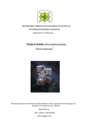
- 58. 57 CHAPTER 4 CASE STUDIES CASE STUDY I : HABITAT 67 Architect: Moshe Safdie Project type: Residential Area: 238000sq ft Place: Montreal, Canada Year of completion: 1967 Fig. 3.46 HABITAT 67 Aerial view This project validates that a single primitive shape that can be strategically gathered and organized to create a lively set of unique private spaces while simultaneously allowing for circulation and social public spaces.
- 59. 58 Fig. 3.47 Plan Fig. 3.48 Site Plan
- 60. 59 Fig. 3.49 Unit plan Fig. 3.50 Two storey unit
- 61. 60 Fig. 3.51 View of HABITAT 67 Habitat 67 is formed using approximately 20x40x10ft concrete rectilinear volumes, which are oriented and connected in specific ways to create varied apartments. Fig. 3.52 Balcony diagram
- 62. 61 Fig. 3.53 Section Fig. 3.54 Isometric section
- 63. 62 Fig. 3.55 At the time of construction At the time of construction, these boxes were an experiment and ultimately a breakthrough in pre-fabricated concrete. For this reason, all the boxes were uniformly mass produced, creating the challenge of designing unique spaces with a single form. Safdie took on the further challenge of giving each apartment a mini-paradise feeling through terraces and outdoor access. The arrangements of the boxes was key to the realization of this goal as they directed the circulation of each apartment. The accumulation of the blocks creates circulation and private exterior spaces in a closely urban context.
- 64. 63 CASE STUDY II : Queen Alia interatonal airport (A modular concept for future expansion) Architect: Foster + Partners Place: Amman, Jordan Area: 65,000 sq ft Type: Public building Queen Alia International Airport is designed to serve as a main gateway to Amman.As it is located in Amman where summer temperatures vary markedly between daytime and nighttime, architects at Foster + Partners used concrete as a main material – high thermal mass provides high passive environmental control. Fig. 3.56 Bird eye view of Queen Alai airport
- 65. 64 Fig. 3.57 Key plan Fig. 3.58 Section Its idealistic yet cellular architecture supports local building expertise and Amman’s climate, therefore integrating strategies which successfully provide efficient passive design. Modular and flexible concept of the terminal allows for future expansion, ensuring annual growth of
- 66. 65 6% and increasing capacity from 3 million to 12.8 million passengers per year by 2030 – the Airport is preordained to be the most important hub for Levant region. Fig. 3.59 Modular Terrace Fig. 3.6 Roof top view
- 67. 66 Plants and trees in open-air courtyards filter pollution and prerequisite air before it is drawn into the system. The large forecourt is designed as a landscaped plaza with seating in shade and allows people to gather while welcoming recurring travelers. Fig. 3.61 Interior view To enable seamless expansion over time, each dome of the tessellated roof canopy is a modular, semi-autonomous unit. They branch out from supporting columns like leaves of a desert palm with the geometric pattern applied to each, representing the veins of a leaf. All facades of the terminal are designed in glass, opening long views to the aircraft. Central building of the terminal contains main areas and public contents – shops, lounges and restaurants.
- 68. 67 CASE STUDY III: Customizable Housing Tower in India Architect: Penda Area: 36000 sq m Project year: 2015 Penda has released the plans for their first project in India. It relies on modular building system, the Pooja Crafted Homes will allow residents of Vijayawada to design their own high-rise apartment by selecting prefabricated modules from a catalogue that will then be inserted into the tower's frame. Fig. 3.61 Housing tower
- 69. 68 Fig. 3.62 View Fig. 3.63 Side view Fig. 3.64 Structural Framework
- 70. 69 Fig. 3.65 Modules The tower, due to break ground in 2016, will be divided into 8 distinct elements: the structure, walls, facade, ceiling & floors, infrastructure, balconies and plants. Much like a modular deferring system, the tower's structural grid and infrastructure will be the only consistent elements in the building. Each home will be uniquely customized by its occupants in a way that will also allow for future modifications.
- 71. 70 Fig. 3.66 Modules in Tower The modules are alternating from different floors, to facade element, to railings and a variety of pots for plants to grow along the home. By choosing their own elements, we offer the owners a tool to become the designers of their individual apartment.
- 72. 71 CASE STUDY IV : Qatar 2022 World Cup ( a modular Demountable Stadium built from shipping containers) Architect: Fenwick Iribarren Architects Place: Southeast of Doha, Qatar Area: 450,000-square-metre Type: Recreation & Entertainment The design of the seventh stadium being constructed for the 2022 FIFA World Cup in Qatar has been revealed. It is designed by Fenwick Iribarren Architects, the Ras Abu Aboud Stadium will be constructed from a series of modified shipping containers meeting within a steel framework, allowing it to be quickly assembled, disassembled and then reassembled in a new location following the conclusion of the event. Fig. 3.67 Exterior view of the stadium
- 73. 72 This setting offers the perfect legacy, capable of being reassembled in a new location in its entirety or built into numerous small sports and cultural venues.All of this in a stadium that transports the atmosphere fans expect at a World Cup and which we will build in a more sustainable way than ever before. I’m delighted with this design and confident that Ras Abu aboud will become a proposal for future mega-event planners. Fig. 3.68 Approach to the stadium The modular design will require scarcer materials, create less waste and reduce the overall carbon footprint compared to a traditional building process, while also reducing building time to as little as three years. The stadium is aiming to achieve a four-star Global Sustainability Assessment System (GSAS) authorization.
- 74. 73 Fig. 3.69 sitting spaces in the stadium Fig. 3.7 Proposed view of the stadium
- 75. 74 The project is expected to located on a 450,000-square-metre waterfront site just southeast of Doha, the 40,000-seat stadium will be broken down into a series of modular blocks, modified shipping containers. The containers will be reformed to contain the various fundamental stadium program elements, including stairs, allowances and bathrooms. Located just 1.5 kilometres from Doha’s Hamad International Airport, the stadium will be made easily accessible to visitors through a dedicated stop on Qatar Rail’s Gold Line and a possible water taxi stop. Fig. 3.71 Location of the stadium
- 76. 75
- 77. 76 CHAPTER 5 CONCLUSION Modular design splits a system in smaller parts so that it can be functional and used separately and more efficiently. It reduces the effort of considering the whole project into account. For mass production, the design of modules includes breaking the built into different repeating units at different levels. A designer can use this the easier way or in the interesting manner. From Research Papers: There are various advantages as prefab modular construction saves time and gives an extremely high quality product even though it doesn't make the construction cheaper, as the controlled environment leads to increase in costs. The modular design as it means, subdivides a building. The spaces created are usually independent of each other,i.e, the might or might not relate to each other. As in case of commercial skyscraper , there are many convention halls, commercial rooms which are not usually owned by an individual/company but it rather out for specific time period. So that the design and placement of these should be done in such a way that they don't interfere with the functioning of the existing offices and also not be totally secluded from them. Referring to the case study of the HABITAT 67, Montreal , Canada ; the stacking of the building blocks are seen in a functional and aesthetic manner giving a dynamic set of unique private spaces while simultaneously allowing for circulation and social public spaces. Referring to the case study of proposal of CUSTAMIZABLE HOUSING TOWER in India the designer thought of a system based on modular building system, selecting the prefabricated modules offers a great amount of flexibility to the residents. Each home will be uniquely customized by its occupants in a way that it will allow for future modifications. Referring to the case study Queen Alia international airport designed by Foster + Partners shows the use of the modern technologies and integrated strategies which provide efficient passive design. Also the dominant use of the repeating modules gives a future expansion and is friendly to the environment due to some passive technologies used in it.
- 78. 77 The futuristic approach of modular design is the key option of upgradation of the upcoming buildings as per required usage. This somehow relates to the retrofitting concept. It’s not just replacing the older technologies with the newer ones but a little more care towards design could allow us to expand the building accordingly with the usage in the future.
- 79. 78 REFERENCES: Source: online https://www.abebooks.com/Retail-Spaces-Therapy-Store-Design- Today/11807419531/bd http://www.iitk.ac.in/nicee/EQTips/EQTip23.pdf https://www.cadpro.com/drafting-software/cad-software-for-parking-lot-designs/ http://www.webpages.uidaho.edu/niatt_labmanual/Chapters/parkinglotdesign/theoryan dconcepts... https://www.archdaily.com/884528/a-modular-demountable-stadium-built-from- shipping-contain... https://www.arch2o.com/language-modular-architecture/ Source: Published Hatch, N.W., 2001. Design rules, volume 1: The power of modularity. Academy of Management Review, 26(1), pp.130-133. Dietz, Albert G. H. (1971) Industrialized Building Systems. Publisher - The MIT press Goldberg, P. (1996) Moshe Safdie: Volume 1. Publisher Images Publishing Group Pty. Ltd Goldberg, P. (2009) Moshe Safdie: Volume 2. Publisher - Images Publishing Group Pty. Ltd