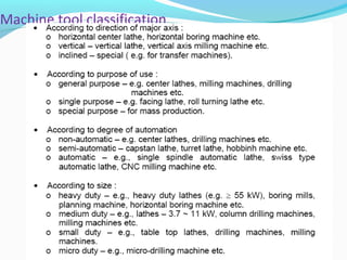
Lathe
•Télécharger en tant que PPT, PDF•
7 j'aime•6,913 vues

Machining is an essential process for finishing workpieces to desired dimensions and surface finish. A lathe allows for gradually removing excess material from a workpiece through cutting tools. Common lathe operations include turning, grooving, chamfering, parting, facing, and knurling. Taper turning can be done through methods like using a form tool, swiveling the compound rest, or a taper attachment. Thread cutting follows a helical path and involves engaging a half-nut to advance the tool.

Recommandé
Contenu connexe
Tendances
Tendances (20)
Similaire à Lathe
Similaire à Lathe (20)
Dernier
Dernier (20)
Lathe
- 2. Machining is an essential process of finishing by which jobs are produced to the desired dimensions and surface finish by gradually removing the excess material from the work piece in the form of chips with the help of cutting tool moved past the work surface. Machining
- 3. Parts of the Lathe
- 4. Machining operation done in lathe Straight turning Grooving Chamfering •Parting off •Facing •Knurling
- 5. Turning .. Excess Material is removed to reduce Diameter Cutting Tool: Turning Tool a depth of cut of 1 mm will reduce diameter by 2 mm
- 7. Facing .. Machine end of job To Reduce Length of Job Feed: in direction perpendicular to work-piece axis Length of Tool Travel = radius of work-piece
- 8. Facing ..
- 9. Knurling
- 10. Grooving Produces a Groove on workpiece Shape of tool shape of groove Also called Form Turning
- 11. Grooving ..
- 12. Parting Cutting workpiece into Two Similar to grooving Parting Tool Hogging – tool rides over – at slow feed Coolant use
- 13. Parting ..
- 14. Chamfering Beveling sharp machined edges Similar to form turning Chamfering tool – 45° Avoid Sharp Edges Make Assembly Easier
- 15. Lathe Accessories Lathe centers, chucks, faceplates Mandrels, steady and follower rests 15
- 16. Lathe Centers Work to be turned between centers must have center hole drilled in each end Provides bearing surface Support during cutting Most common have solid Morse taper shank 60º centers, steel with carbide tips Care to adjust and lubricate occasionally 16
- 17. Lathe Centers 17
- 18. For holding cylindrical stockFor holding cylindrical stock centered.centered. For facing/center drilling the end ofFor facing/center drilling the end of your aluminum stockyour aluminum stock Four-Jaw Chuck This is independent chuck generally has four jaws, which are adjusted individually on the chuck face by means of adjusting screws Three jaw chuck
- 19. Thin jobs can be held by means of magnetic chucks. Collet Chuck Magnetic Chuck Collet chuck is used toCollet chuck is used to hold small workpieceshold small workpieces Thin jobs can be heldThin jobs can be held by means of magneticby means of magnetic chucks.chucks.
- 20. Used to hold round, square, hexagonal, and irregularly shaped workpieces Has four jaws Each can be adjusted independently by chuck wrench Jaws can be reversed to hold work by inside diameter 20 Four-Jaw Independent Chuck
- 21. Collet Chucks Most accurate chuck Used for high-precision work Spring collets available to hold round, square, or hexagon-shaped workpieces Each collet has range of only few thousandths of an inch over or under size stamped on collet 21
- 22. Magnetic Chucks Used to hold iron or steel parts that are too thin or may be damaged if held in conventional chuck Used only for light cuts and for special grinding applications 22
- 23. Faceplates 23
- 24. Steadyrest Used to support long work held in chuck or between lathe centers Located on and aligned by ways of the lathe Positioned at any point along lathe bed Three jaws tipped with plastic, bronze or rollers may be adjusted to support any work diameter with steadyrest capacity 24
- 25. Steadyrest 25
- 26. Follower Rest 26
- 27. Mandrel Holds internally machined workpiece between centers so further machining operations are concentric with bore Several types, but most common Plain mandrel Expanding mandrel Gang mandrel Stub mandrel 27
- 28. 28 Mandrel
- 29. Direct & Indirect speeds in Lathe BACKGEAR As its name implies, "backgear" is a gear mounted at the back of the headstock that allows the spindle to rotate slowly. Screw-cutting requires slow speeds, typically between 25 to 50 r.p.m. To tackle heavy-duty drilling, big-hole boring
- 31. Advantages
- 32. Disadvantages Some power is lost due to friction of gears All -geared lathes are costlier than the belt driven lathe owing to more complicated gear and lever mechanism. In case of overloading the machine, for having no arrangement of belt slipping, there is little possibility to prevent damage to parts
- 33. Operating condition in a lathe Cutting speed Feed Depth of cut 1-Cutting speed In a lathe, for the turning operation, cutting speed is the peripheral speed of the work piece past the cutting tool. Expressed in meters/minute. Cutting speed= m/min Where D= diameter of the work piece in mm. N=rpm of the work
- 34. Cutting Speed The Peripheral Speed of Work-piece past the Cutting Tool =Cutting Speed D – Diameter (mm) N – Revolutions per Minute (rpm) m/min 1000 ND v π =
- 35. Feed so– the distance the tool advances for every rotation of workpiece (mm/rev)
- 36. 2-Feed The feed of a cutting tool in a lathe work is the distance the tool advances for each revolution of the work. Feed is expressed as mm/revolution.
- 37. Depth of Cut perpendicular distance between machined surface and uncut surface of the Work-piece t = (D1 – D2)/2 (mm)
- 39. Machining time The time required to machine a component is called MACHINING TIME. Machining time depends upon Size of the work piece Amount of material removed and The operating condition(speed, feed, depth of cut) Consider the feed and speed(f×N) the feed rate in mm/min.
- 40. It gives the distance that the tool moves (f×N) in mm is one minute. Hence , for a distance L , the time required for one complete cut, “t” in minute is given by t= minute Alternative If “f” is the feed of the job per revolution expressed in mm/revolution and L is the length of the job in mm , then number of revolutions of the job required for a complete cut will be
- 41. If the rpm of the work is N , time taken to revolve the job through number of revolution for a complete cut will be: There fore time taken for a complete cut t= minute Problem -1 A mild steel rod having 50 mm diameter and 500 mm length is to be turned on a lathe. Determine the machining time to reduce the rod to 45 mm in one pass when cutting speed is 30 m/min and a feed of 0.7 mm/rev is used. Solution Given data: D = 50 mm, Lj = 500 mm v = 30 m/min, f = 0.7 mm/rev Substituting the values of v and D in V = ΠDN/1000 M/min Required spindle speed as: N = 191 rpm
- 42. Tapers and taper turning A taper may be defined as a uniform increase or decrease in diameter of a piece of work measured along its length. In a lathe taper turning means to produce a conical surface by gradual reduction in diameter from a cylindrical work piece. D1= larger diameter of taper in mm D2= smaller diameter of taper in mm L= length of tapered part in mm 2α= full taper angle α=angle of taper or half taper angle
- 43. Taper Turning Taper: L DD 2 tan 21 − =α
- 44. The amount of taper in a work piece is usually specified by the ratio of the difference in diameters of the taper to its length. This is termed as the CONICITY and it is designated by the letter K. L DD K 21 − =
- 45. Taper Turning.. MethodsMethods Form Tool Swiveling Compound Rest Taper Turning Attachment Simultaneous Longitudinal and Cross Feeds Tailstock set over
- 46. Taper turning using a form tool
- 47. Shape of the tool is remain same as the shape of the component to be produced. Accuracy of taper produce depends on accuracy of taper present on tool Width of tool must be greater than or equal to the length of workpiece to be taper turned. Maximum length of component which can be taper turned is 20 mm only Only external taper turning is possible.
- 48. Limitation- This method is limited only for short length taper. Because the metal is removed by the entire cutting edge, and only increase in the length of the taper will necessitate the use of a wider cutting edge. This will require excessive cutting pressure, which may distort the work due to vibration and spoil the work piece.
- 49. Taper turning by swiveling the compound rest
- 50. The compound rest has a circular base graduated in degrees, which can be swiveled at any angle. While turning a taper, the base of compound rest is swiveled through an angle equal to the half taper angle. The tool is then fed by hand. Once the compound rest is set at the desired half taper angle, rotation of the compound slide screw will cause the tool to be fed at that angle and generate a corresponding taper.
- 51. This method is limited to turn a short but steep taper owing to the limited movement of the cross slide. But a small taper may also be turned. The compound rest may be swiveled at 45 degree on turn a steep taper. The movement of the tool in this method being purely controlled by hand, this gives a low production capacity and poorer surface finish. The setting of the compound rest is done by swiveling the rest at the half taper angle, if this is already known. If the diameter of the small and large end and length of taper are known, the half taper angle can be calculated.
- 52. 1. calculate the compound rest angle for turning short taper of 1:15. sol. Let α be the angle at which the compound rest will be set tan α = 152 1 2 × = − l dD .91.1 30 1 tan 01 Ans= =∴ − α
- 53. 3. Calculate the compound rest angle to turn a short taper of 1mm per 12mm. Sol. Given taper : 1 mm per 12mm 04167.0 122 1 2 tan = × = − = l dD α Ans0 386.2=∴α
- 54. Determine the angle at which the compound rest would be swiveled for cutting a taper on a work piece having a length of 150 mm and outside diameter 80 mm. The smallest diameter on the tapered end of the rod should be 50 mm and the required length of the tapered portion is 80 mm. Solution Given data: D1 = 80 mm, D2 = 50 mm, Lj = 80 mm (with usual notations) tan α = (80-50) / 2×80 or α = 10.620 The compound rest should be swiveled at 10.62o
- 55. Taper turning by a taper attachment
- 56. The principle of turning taper by a taper attachment is to guide the tool in a straight path set at an angle to the axis of rotation of the work piece, while the work is being revolved between centers or by a chuck aligned to the lathe axis. A taper turning attachment consists essentially of a bracket or frame which is attached to the rear end of the lathe bed and supports a guide bar pivoted at the centers. The bar having graduations in degrees may be swiveled on either side of the zero graduation and is set at the desired angle with the lathe axis.
- 57. When the taper turning attachment is used, the cross slide is first made free from the lead screw by removing the binder screw. The rear end the cross slide is then tightened with the guide block by means of a bolt. When the longitudinal feed is engaged, the tool mounted on the cross slide will follow the angular path, as the guide block will slide on the gear bar at an angle to the lathe axis. The required depth of cut is given by the compound slide which is placed at right angles to the lathe axis.
- 58. The guide bar must be set at half taper angle and the taper on the work must be converted in degrees. The maximum angle through which the guide bar may be swiveled is 10 degree to 12 degree on either side of the centre line. If the diameters D,d and the length L of the taper are specified, the angle of swiveling the guide bar can be determined from equation tanα=
- 59. The advantage of using a taper turning attachment are- 1-The alignment of live and dead centers being not disturbed, both straight and taper turning may be performed on a work piece in one setting without much loss of time. 2-once the taper is set, any length of a piece of work may be turned with in its limit. 3-very steep taper on a long work piece may be turned, which cannot be done by any other method. 4-accurate taper on a large number of work pieces may be turned. 5-internal tapers can be turned with ease.
- 60. Taper turning by combining feeds Taper turning by combining feeds is a more specialized method of turning taper. In certain lathes both longitudinal and cross feeds may be engaged simultaneously causing the tool to follow a diagonal path which is the resultant of the magnitude of the two feeds.
- 63. AB BCsin α = From fig. In Δ le ABC , For small angles sin α ≈ tan α ; BC = amount of set over and AB = overall length of work piece set over , S = BC = AB tan α S = L tan α = L (BC/l) = L(D-d)/2l
- 64. The length of work is 300 mm, the amount of taper is 1 : 25. Find the tail stock set over required 50 1 252 1 tan = × =α set over, S = L tanα mm6 50 1 300 =×=
- 65. Q. A component having 400 mm length in which central 150 mm length of component can be taper turned to an angle of 4 Degree. Which of the Taper turning Method is used for this ? Ans: Compound and taper attachment method offsets s == = 28 400 4tan Maximum offset will produced on tailstock is 10 mm The length of taper part is 150 mm but by form tool method we can produce taper up to 20 mm length only
- 66. Thread cutting There are a large number of thread forms that can be machined in lathe such as Whitworth, Acme, ISO metric, etc. Thread cutting can be considered as turning only since the path to be travelled by the cutting tool is helical
- 68. Single and Multistart thread
- 69. Right-hand thread Helical ridge of uniform cross section onto which nut is threaded in clockwise direction When cut on lathe, tool advanced from right to left Left-hand thread Helical ridge of uniform cross section onto which nut is threaded in counterclockwise direction When cut on lathe, tool advanced from left to right
- 70. OPERATION
- 71. Half-nut
- 72. summary Lathe is the most important and common machine tool found in practically all machine shops. A large variety of lathes have been developed to cater for different processing requirements. A lathe consists of a bed, headstock, tailstock and a carriage as major components along with a few other items that provide the necessary support and motions.
- 73. summary A variety of chucks such as universal 3-jaw, independent 4-jaw, and faceplate, are used to locate and support work pieces in a lathe for common machining applications. There are a variety of tools available depending upon the type of surface that needs to be generated. There are a large variety of operations such as turning, facing, knurling, contouring, etc. that can be carried out in a lathe. In fact practically all types of surfaces can be generated in a lathe.
- 74. summary Taper turning is a special type of operation that requires the tool to be moved in two different direction simultaneously to generate the surface. For this purpose, a variety of methods are used in a lathe such as compound slide, tailstock offset or a special attachment. Precision threads can be cut in a lathe using the lead screw and special methods
- 75. There are various special attachments such as milling attachment, grinding attachment, etc. have been developed that enhance the range of surfaces that can be generated in a lathe. Machining time for different operations can be estimated using the cutting process parameters and the geometry of the part summary