[W f stoecker]_refrigeration_and_a_ir_conditioning_(book_zz.org)
1. CHAPTER 2 - THERMAL PRINCIPLES
Page 1 of 5
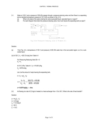
2-1. Water at 120 C and a pressure of 250 kPa passes through a pressure-reducing valve and then flows to a separating
tank at standard atmospheric pressure of 101.3 kPa, as shown in Fig. 2-14.
(a) What is the state of the water entering the valve (subcooled liquid, saturated liquid, or vapor)?
(b) For each kilogram that enters the pressure-reducing valve, how much leaves the separating tank as vapor?
Solution:
(a) From Fig. 2-2, a temperature of 120 C and pressure of 250 kPa water lies in the sub-cooled regiom. so it is a sub-
cooled liquid.
(b) At 120 C, h1
= 503.72 kJ/kg from Table A-1
For Pressuring Reducing Valve Dh = 0
h2
= h1
At 101.3 kPa, Table A-1, hf
= 419.06 kJ/kg
hg
= 2676 kJ/kg
Let x be the amount of vapor leaving the separating tank.
h = hf
+ x(hg
- hf
)
419.062676
419.06503.72
hh
hh
x
fg
f
−
−
=
−
−
=
x = 0.0375 kg/kg - - - Ans.
2-2. Air flowing at a rate of 2.5 kg/s is heated in a heat exchanger from -10 to 30 C. What is the rate of heat transfer?
Solution:
q = mcp
(t2
- t1
)
m = 2.5 kg/s
cp
= 1.0 kJ/kg.K
t2
= 30 C
t1
= -10 C
2. CHAPTER 2 - THERMAL PRINCIPLES
Page 2 of 5
Then,
q = (2.5)(1.0)(30 + 10)
q = 100 kw - - - Ans.
2-3. One instrument for measuring the rate of airflow is a venturi, as shown in Fig. 2-15, where the cross-sectional area is
reduced and the pressure difference between position A and B measured. The flow rate of air having a density of 1.15
kg/m
3
is to be measured in a venturi where the area of position A is 0.5 m
2
and the area at b is 0.4 m
2
. The deflection
of water (density = 1000 kg/m3) in a manometer is 20 mm. The flow between A and B can be considered to be
frictionless so that Bernoulli’s equation applies.
(a) What is the pressure difference between position A and B?
(b) What is the airflow rate?
Solution:
(a) Bernoulli equation for manometer
B
B
A
A
gz
p
gz
p
+
ρ
=+
ρ
pA
- pB
= ρg(zB
-zA
)
zB
- zA
= 20 mm = 0.020 m
g = 9.81 m/s
2
ρ = 1000 kg/m
3
pA
- pB
= (1000 kg/m
3
)(9.81 m/s
2
)(0.020 m)
pA
- pB
= 196.2 Pa - - - Ans.
(b) Bernoulli Equation for Venturi
constant
2
Vp 2
=+
ρ
3. CHAPTER 2 - THERMAL PRINCIPLES
Page 3 of 5
2
Vp
2
Vp
2
BB
2
AA
+
ρ
=+
ρ
( )2
A
2
B2
1
BA VVpp −ρ=−
But m = ρAA
VA
= ρAB
VB
AA
VA
= AB
VB
AA = 0.5 m2 ans AB = 0.4 m2
Then
0.5VA
= 0.4VB
VA
= 0.8VB
( ) ( )[ ]2
B
2
B
3
2
1
BA 0.8VVkg/m1.15Pa196.2pp −==−
VB
= 30.787 m/s
Air Flow Rate = AB
VB
= (0.4 m
2
)(30.787 m/s)
= 12.32 m
3
/s - - - Ans.
2-4. Use the perfect-gas equation with R = 462 J/kg.K to compute the specific volume of saturated vapor at 20 C. Compare
with data of Table A-1.
Solution:
Perfect-Gas Equation:
RTp =ν
p
RT
=ν
At 20 C, Table A-1, Saturation Pressure = 2.337 kPa = 2337 Pa.
Specific volume of saturated vapor = 57.84 m
3
/kg
T = 20 C + 273 = 293 K
( )( )
Pa2337
K293J/kg.K462
=ν
/kgm57.923 3
=ν
( )100%
57.84
57.8457.923
Deviation
−
=
Deviation = 0.1435 %
2-5. Using the relationship shown on Fig. 2-6 for heat transfer when a fluid flows inside tube, what is the percentage
increase or decrease in the convection heat-transfer coefficient hc
if the viscosity of the fluid is decreased 10 percent.
4. CHAPTER 2 - THERMAL PRINCIPLES
Page 4 of 5
Solution:
Figure 2-6.
0.40.8
Pr0.023ReNu =
where:
µ
ρ
=
VD
Re
k
c
Pr
pµ
=
k
Dh
N c
=u
Then,
0.4
p2
0.8
2
0.4
p1
0.8
1
c2
c1
k
cVD
0.023
k
cVD
0.023
k
Dh
k
Dh
µ
µ
ρ
µ
µ
ρ
=
0.4
1
2
c2
c1
h
h
µ
µ
=
If viscosity is decreased by 10 %
0.9
1
2
=
µ
µ
Then,
( )0.4
c2
c1
h
h
9.0=
hc2
= 1.043hc1
( )100%
h
hh
Increase
c1
c1c2 −
=
Increase = (1.043 - 1)(100 %)
Increase = 4.3 % - - - Ans.
2-6. What is the order of magnitude of heat release by convection from a human body when the air velocity is 0.25 m/s and
its temperature is 24 C?
Solution:
Using Eq. (2-12) and Eq. (2-18)
C = hc
A( ts
- ta
)
hc
= 13.5V
0.6
V = 0.25 m/s
hc
= 13.5(0.25)
0.6
= 5.8762 W/m
2
.K
5. CHAPTER 2 - THERMAL PRINCIPLES
Page 5 of 5
Human Body: A = 1.5 to 2.5 m
2
use 1.5 m
2
ts
= 31 to 33 C use 31 C
C = (5.8762 W/m
2
.K)(1.5 m
2
)(31 C - 24 C)
C = 61.7 W
Order of Magnitude ~ 60 W - - - Ans.
2-7 What is the order of magnitude of radiant heat transfer from a human body in a comfort air-conditioning situation?
Solution:
Eq. 2-10.
( )4
2
4
1A21 TTFAFq −εσ=−
Surface area of human body = 1.5 to 2.5 m
2
use 1.5 m
2
AFε
FA
= (1.0)(0.70)(1.5 m
2
) - 1.05 m
2
s = 5.669x10
-8
W/m
2
.K
4
T1
=31 C + 273 = 304 K
T2
= 24 C + 273 = 297 K
q1-2
= (5.669x10
-8
)(1.05)(304
4
- 297
4
)
q1-2
= 45 W
Order of Magnitude ~ 40 W - - - Ans.
2-8. What is the approximate rate of heat loss due to insensible evaporation if the skin temperature is 32 C, the vapor
pressure is 4750 Pa, and the vapor pressure of air is 1700 Pa? The latent heat of water is 2.43 MJ/kg; Cdiff
= 1.2x10
-9
kg/Pa.s.m
2
.
Solution:
Equation 2-19.
qins
= hfg
ACdif
f( ps
- pa
)
Where:
A = 2.0 m
2
average for human body area
hfg
= 2.43 MJ/kg = 2,430,000 J/kg
ps
= 4750 Pa
pa
= 1700 Pa
Cdiff
= 1.2x10
-9
kg/Pa.s.m
2
qins
= (2,430,000)(2.0)(1.2x10
-9
)(4750 - 1700)
qins
= 18 W - - - Ans.
- 0 0 0 -
6. CHAPTER 3- PSYCHROMETRY AND WETTED-SURFACE HEAT TRANSFER
Page 1 of 9
3-1 Calculate the specific volume of an air-vapor mixture in cubic meters per kilogram of dry air when the
following conditions prevail: t = 30 C, W = 0.015 kg/kg, and pt
= 90 kPa.
Solution:
Equation 3-4.
st
a
a
a
pp
TR
p
TR
−
==ν
T = 30 C + 273 = 303 K
Ra
= 287 J/kg.K
Pt
= 90 kPa = 90,000 Pa
Equation 3-2
st
s
pp
0.622p
W
−
=
s
s
p90
0.622p
0.015
−
=
1.35 - 0.15ps
= 0.622ps
ps
= 2.1193 kPa
( )( )
2119.390000
303287
pp
TR
st
a
−
=
−
=ν
νννν = 0.99 m
3
/kg - - - Ans.
3-2. A sample of air has a dry-bulb temperature of 30 C and a wet-bulb temperature of 25 C. The barometric
pressure is 101 kPa. Using steam tables and Eqs. (3-2), (303), and (3-5), calculate (a) the humidity ration if
this air is adiabatically saturated, (b) the enthalpy of air if it is adiabatically saturated, (c) the humidity ratio of
the sample using Eq. (3-5), (d) the partial pressure of water vapor in the sample, and (e) the relative
humidity.
Solution:
Eq. 3-2.
st
s
pp
0.622p
W
−
=
Eq. 3-3.
h = cp
t + Whg
Eq. 3-5
h1
= h2
- (W2
- W1
)hf
h1
= cp
t1
+ Whg1
hg1
at 30 C = 2556.4 kJ/kg
t1 = 30 C
cp = 1.0 kJ/kg.K
h1
= (1)(30) + 2556.4W1
h1
= 30 + 2556.4W1
7. CHAPTER 3- PSYCHROMETRY AND WETTED-SURFACE HEAT TRANSFER
Page 2 of 9
h2
= cp
t2
+ Whg2
hg2
at 25 C = 2547.3 kJ/kg
t2
= 25 C
cp
= 1.0 kJ/kg.K
h2
= (1)(25) + 2547.3W2
h2
= 25 + 2547.3W2
hf
at 25 C = 125.66 kJ/kg
Then:
h1
= h2
- (W2
- W1
)hf
30 + 2556.4W1
= 25 + 2547.3W2
- (W2
- W1
)(125.66)
5 = 2421.64W2
- 2430.74W1
But,
st
s
2
pp
0.622p
W
−
=
ps at 25 C = 3.171 kPa
( )
3.171-101
3.1710.622
W2 =
W2
= 0.0201 kg/kg
5 = 2421.64(0.0201) - 2430.74W1
W1
= 0.018 kg/kg
(a) Humidity Ratio
W2
= 0.0201 kg/kg - - - Ans.
(b) h2
= cp
t2
+ W2
hg2
h2
= (1)(25) + (0.0201)(2547.3)
h2
= 76.2 kJ/kg - - - Ans.
(c) Humidity Ratio
W1
= 0.018 kg/kg - - - Ans.
(d) ps1
st
s
1
pp
0.622p
W
−
=
s
s
p101
0.622p
0
−
=018.
ps1
= 2.84 kPa
ps1
= 2840 kPa - - - Ans.
8. CHAPTER 3- PSYCHROMETRY AND WETTED-SURFACE HEAT TRANSFER
Page 3 of 9
(e) At 30 C, ps
= 4.241 kPa
Relative Humidity = (2.84 kPa / 4.241 kPa)(100%)
Relative Humidity = 67 % - - - Ans.
3-3 Using humidity ratios from the psychrometric chart, calculate the error in considering the wet-bulb line to be
the line of constant enthalpy at the point of 35 C dry-bulb temperature and 50 percent relative humidity.
Solution:
Dry-bulb Temperature = 35 C
Relative Humidity = 50 %
Fig. 3-1, Psychrometric Chart.
At constant enthalpy line: Wet-bulb = 26.04 C
At wet-bulb line = Wet-bulb = 26.17 C
Error = 26.17 C - 26.04 C
Error = 0.13 C
3-4. An air-vapor mixture has a dry-bulb temperature pf 30 C and a humidity ratio of 0.015. Calculate at two
different barometric pressures, 85 and 101 kPa, (a) the enthalpy and (b) the dew-point temperature.
Solution:
At 30 C, ps
= 4.241 kPa, hg
= 2556.4 kJ/kg
(a) h = cp
t + Whg
For 85 and 101 kPa
cp
= 1.0
t = 30 C
W = 0.015 kg/kg
hg
= 2556.4 kJ/kg
h = (1.0)(30) + (0.015)(2556.4)
h = 68.3 kJ/kg
(b) For dew-point:
st
s
pp
0.622p
W
−
=
at 85 kPa
st
s
pp
0.622p
0.015
−
=
ps
= 2.0016 kPa
9. CHAPTER 3- PSYCHROMETRY AND WETTED-SURFACE HEAT TRANSFER
Page 4 of 9
Dew-Point = 17.5 C - - - Ans.
at 101 kPa
st
s
pp
0.622p
0.015
−
=
ps
= 2.3783 kPa
Dew-Point = 20.3 C - - - Ans.
3-5. A cooling tower is a device that cools a spray of water by passing it through a stream of air. If 15 m
3
/s of air is
at 35 C dry-bulb and 24 C wet-bulb temperature and an atmospheric pressure of 101 kPa enters the tower
and the air leaves saturated at 31 C, (a) to what temperature can this airstream cool a spray of water
entering at 38 C with a flow rate of 20 kg/s and (b) how many kilograms per second of make-up water must
be added to compensate for the water that is evaporated?
Solution:
At 35 C dry-bulb, 24 C wet-bulb.
Fig. 3-1, Psychrometric Chart
h1
= 71.524 kJ/kg,
ν1
= 0.89274 m
3
/kg
W1
= 0.0143 kg/kg
At 31 C saturated, Table A-2.
h2
= 105 kJ/kg
W2
= 0.0290 kg/kg
Then;
m = (15 m
3
/s) / (0.89274 m
3
/kg) = 16.8022 kg/s
(a) tw1
= 38 C
mw
= 20 kg/s
cpw
= 4.19 kJ/kg.K
mw
cpw
(tw1
- tw2
) = m(h2
- h1
)
(20)(4.19)(38 - tw2
) = (16.8022)(105 - 71.524)
tw2
= 31.3 C - - - Ans.
(b) Make-Up Water = mm
mm
= m(W2
- W1
)
mm
= (16.8022)(0.0290 - 0.0143)
mm
= 0.247 kg/s - - - Ans.
3-6. In an air-conditioning unit 3.5 m
3
/s of air at 27 C dry-bulb temperature, 50 percent relative humidity, and
10. CHAPTER 3- PSYCHROMETRY AND WETTED-SURFACE HEAT TRANSFER
Page 5 of 9
standard atmospheric pressure enters the unit. The leaving condition of the air is 13 C dry-bulb temperature
and 90 percent relative humdity. Using properties from the psychrometric chart, (a) calculate the refrigerating
capacity inkilowatts and (b) determine the rate of water removal from the air.
Solution:
At 27 C dry-buld, 5 Percent Relative Humidity
h1
= 55.311 kJ/kg,
ν1
= 0.86527 m
3
/kg
W1
= 0.0112 kg/kg
At 13 C Dry-Bulb, 90 Percent Relative Humidity
h2
= 33.956 kJ/kg
W2
= 0.0084 kg/kg
m = (3.5 m
3
/s)/(0.86526 m
3
/kg) = 4.04498 kg/s
(a) Refrigerating Capacity
= m(h1
- h2
)
= (4.04498)(55.311 - 33.956)
= 86.38 kW - - - Ans.
(b) Rate of Water Removal
= m(W1
- W2
)
= (4.04498)(0.0112 - 0.0084)
= 0.0113 kg/s - - - Ans.
3-7. A stream of outdoor air is mixed with a stream of return air in an air-conditioning system that operates at 101
kPa pressure. The flow rate of outdoor air is 2 kg/s, and its condition is 35 C dry-bulb temperature and 25 C
wet-bulb temperature. The flow rate of return air is 3 kg/s, and its condition is 24 C and 50 percent relative
humidity. Determine (a) the enthalpy of the mixture, (b) the humidity ratio of the mixture, (c) the dry-bulb
temperature of the mixture from the properties determined in parts (a) and (b) and (d) the dry-bulb
temperature by weighted average of the dry-bulb temperatures of the entering streams.
Solutions:
Use Fig. 3-1, Psychrometric Chart
At 35 C Dry-Bulb, 24 C Wet-Bulb
h1
= 75.666 kJ/kg, m1
= 2 kg/s
W1
= 0.0159 kg/kg
At 24 C Dry-Bulb, 50 Percent Relative Humidity
h2
= 47.518 kJ/kg, m2
= 3 kg/s
W2
= 0.0093 kg/kg
(a)
( )( ) ( )( )
32
47.518375.6662
hm
+
+
=
hm
= 58.777 kJ/kg - - - Ans.
11. CHAPTER 3- PSYCHROMETRY AND WETTED-SURFACE HEAT TRANSFER
Page 6 of 9
(b)
( )( ) ( )( )
32
0.009330.01592
Wm
+
+
=
Wm
= 0.1194 kg/kg - - - Ans.
(c) At 58.777 kJ/kg and 0.01194 kg/kg.
From Psychrometric Chart, Fig. 3-1.
Dry-Bulb Temperature = 28.6 C - - - Ans.
(d)
( )( ) ( )( )
32
243352
tm
+
+
=
tm
= 28.4 C - - - Ans.
3-8. The air conditions at the intake of an air compressor are 28 C, 50 percent relative humidity, and 101 kPa.
The air is compressed to 400 kPa, then sent to an intercooler. If condensation of water vapor from the
compressed air is to be prevented, what is the minimum temperature to which the air can be cooled in the
intercooler?
Solution: At 28 C, ps
= 3.778 kPa
At 50 percent relative humidity, ps
= (0.5)(3.778 kPa) = 1.889 kPa
st
s
pp
0.622p
W
−
=
Moisture ratio is constant
at 101 kPa
( )
1.889101
1.8890.622
W
−
=
W = 0.011855 kg/kg
at 400 kPa, determine ps
s
s
p
0.622p
0.011855
−
=
400
ps
= 7.4812 kPa
From Table A-1.
Dew-Point = 40.3 C - - - Ans.
12. CHAPTER 3- PSYCHROMETRY AND WETTED-SURFACE HEAT TRANSFER
Page 7 of 9
3-9. A winter air-conditioning system adds for humidification 0.0025 kg/s of saturated steam at 101 kPa pressure
to an airflow of 0.36 kg/s. The air is initially at a temperature of 15 C with a relative humidity of 20 percent.
What are the dry- and wet-bulb temperatures of the air leaving the humidifier?
Solution:
At 15 C Dry-Bulb, 20 Percent Relative Humidity
h1
= 20.021 kJ/kg
W1
= 0.0021 kg/kg
At 101 kPa steam, hfg
= 2675.85 kJ/kg
ms
= 0.0025 kg/s
m = 0.36 kg/s
ms
= m(W2
- W1
)
0.0025 = 0.36(W2
- 0.002)
W2
= 0.00894 kg/kg
m(h2
- h1
) = ms
hg
(0.36)(h2 - 20.021) = (0.0025)(2675.85)
h2
= 38.6 kJ/kg
Fig. 3-1, Psychrometric Chart
W2
= 0.00894 kg/kg
h2
= 38.6 kJ/kg
Dru-Bulb Temperature = 16.25 C
Wet-Bulb Temperature = 13.89 C
3-10. Determine for the three cases listed below the magnitude in watts and the direction of transfer of sensible
heat [ using Eq. (3-8)], latent heat [ using Eq. (3-9)], and total heat [ using Eq. (3-14)]. the area is 0.15 m
2
and
hc
= 30 W/m
2
.K. Air at 30 C and 50 percent relative humidity is in contact with water that is at a temperature
of (a) 13 C, (b) 20 C, and (c) 28 C.
Solution:
Equation 3-8.
dqs
= hc
dA(ti
- ta
)
Equation 3-9.
dqL
= hD
dA(Wi
- Wa
)hfg
Equarion 3-14.
)h(h
c
dAh
dq ai
pm
c
t −=
At 30 C, 50% Relative Humidity
ha
= 63.965 kJ/kg = 63,965 J/kg
Wa
= 0.0134 kg/kg
(a) 13 C
dqs
= hc
dA(ti
- ta
)
dqs
= (30)(0.15)(13 - 30)
13. CHAPTER 3- PSYCHROMETRY AND WETTED-SURFACE HEAT TRANSFER
Page 8 of 9
dqs
= -76.5 W - - - Ans.
dqL
= hD
dA(Wi
- Wa
)hfg
Wi
at 13 C = 0.00937 kg/kg from Table A-2
hfg
at 13 C = 2,470,840 J/kg
hD
= hc
/ cpm
cpm
= 1020 kJ/kg.K
hD
= 30 / 1020 = 0.029412
dqL
= (0.029412)(0.15)(0.00937 - 0.0134)(2,470,840)
dqL
= -43.93 W - - - Ans.
hi
at 13 C = 36,719 J/kg from Table A-2
( )( )( )63,96536,719
1020
0.1530
)h(h
c
dAh
dq ai
pm
c
t −=−=
dqt
= -120.2 W - - - Ans.
(b) 20 C
dqs
= hc
dA(ti
- ta
)
dqs
= (30)(0.15)(20 - 30)
dqs
= -45 W - - - Ans.
dqL
= hD
dA(Wi
- Wa
)hfg
Wi
at 20 C = 0.01475 kg/kg from Table A-2
hfg
at 20 C = 2,454,340 J/kg
hD
= hc
/ cpm
cpm
= 1020 kJ/kg.K
hD
= 30 / 1020 = 0.029412
dqL
= (0.029412)(0.15)(0.01475 - 0.0134)(2,454,340)
dqL
= 14.62 W - - - Ans.
hi
at 20 C = 57,544 J/kg from Table A-2
( )( )( )63,96557,544
1020
0.1530
)h(h
c
dAh
dq ai
pm
c
t −=−=
dqt
= -28.33 W - - - Ans.
(c) 28 C
dqs
= hc
dA(ti
- ta
)
dqs
= (30)(0.15)(28 - 30)
dqs
= -9.0 W - - - Ans.
14. CHAPTER 3- PSYCHROMETRY AND WETTED-SURFACE HEAT TRANSFER
Page 9 of 9
dqL
= hD
dA(Wi
- Wa
)hfg
Wi
at 28 C = 0.02422 kg/kg from Table A-2
hfg
at 28 C = 2,435,390 J/kg
hD
= hc
/ cpm
cpm
= 1020 kJ/kg.K
hD
= 30 / 1020 = 0.029412
dqL
= (0.029412)(0.15)(0.02422 - 0.0134)(2,435,390)
dqL
= 116.3 W - - - Ans.
hi
at 28 C = 89,952 J/kg from Table A-2
( )( )( ),96589,952
1020
0.1530
)h(h
c
dAh
dq ai
pm
c
t 63−=−=
dqt
= 114.6 W - - - Ans.
- 0 0 0 -
15. CHAPTER 4 - HEATING AND COOLING LOAD CALCULATION
Page 1 of 8
4-1 The exterior wall of a single-story office building near Chicago is 3 m high and 15 m long. The wall consists
of 100-mm facebrick, 40-mm polystyrene insulating board. 150-mm lightweight concrete block, and an
interior 16-mm gypsum board. The wall contains three single-glass windows 1.5 n high by 2 m long.
Calculate the heat loss through the wall at design conditions if the inside temperature is 20 C.
Solution:
Table 4-3, Design Outdoor is -18 C for Chicago.
For the wall:
Area, A = (3 m)(15 m) - (3)(1.5 m)(2 m) = 36 m
2
.
Resistance: Table 4-4.
Outside Air Film 0.029
Facebrick, 100 mm 0.076
Polystyrene Insulating Board, 40 mm 1.108
Lightweight Concrete Block, 150 mm 0.291
Gypsum Board, 16 mm 0.100
Inside Air Film 0.120
====
Rtot
= 1.724 m
2
.K/ W
Wall:
( )2018
1.724
36
t
Rtot
A
q −−=∆=
q = -794 Watts
For the glass:
Area A = (3)(1.5 m0(2 m) = 9 m
2
Table 4-4, U = 6.2 W/m
2
.K
q = UA∆t = (6.2)(9)(-18 - 20)
q = -2,120 Watts
Total Heat Loss Thru the Wall = -794 W -2,120 W
= -2,194 Watts - - - Ans
.
4-2. For the wall and conditions stated in Prob. 4-1 determine the percent reduction in heat loss through the wall if
(a) the 40 mm of polystyrene insulation is replaced with 55 mm of cellular polyurethane, (b) the single-glazed
windows are replaced with double-glazed windows with a 6-mm air space. (c) If you were to choose between
modification (a) or (b) to upgrade the thermal resistance of the wall, which would you choose and why?
Solution
(a) Resistance: Table 4-4
Outside Air Film 0.029
Facebrick, 100 mm 0.076
Cellular Polyurethane, 55 mm 2.409
Lightweight Concrete Block, 150 mm 0.291
Gypsum Board, 16 mm 0.100
Inside Air Film 0.120
=====
Rtot
= 3.025 m
2
.K/W
16. CHAPTER 4 - HEATING AND COOLING LOAD CALCULATION
Page 2 of 8
Wall:
( )2018
3.025
36
t
Rtot
A
q −−=∆=
q = - 452 Watts
New Total Heat Loss Thru Wall
q = - 452 W - 2,120 W
q = - 2,572 W
( ) ( )( )%100
W2,914
W2,572W2,914
%Reduction
−
−−−
=
% Reduction = 11.74 %- - - Ans.
(b) For the glass: (Double-Glazed)
Table 4-4, U = 3.3 W/m
2
.K
q = UA∆t = (3.3)(9)(-18 - 20)
q = -1,129 Watts
New Total Heat Loss Thru Wall
q = - 794 W - 1,129 W
( ) ( )( )%100
W2,914
W,923W2,914
%Reduction
−
−−−
=
1
% Reduction = 34 %- - - Ans.
(c) Choose letter b --- Ans.
4-3 An office in Houston, Texas, is maintained at 25 C and 55 percent relative humidity. The average occupancy
is five people, and there will be some smoking. Calculate the cooling load imposed by ventilation
requirements at summer design conditions with supply air conditions set at 15 C and 95 percent relative
humidity if (a) the recommended rate of outside ventilation air is used and (b) if a filtration device of E = 70
precent is used.
Solution:
Table 4-3, Houston Texas
Summer Deisgn Conditions
Dry-Bulb = 34 C
Wet-Bulb = 25 C
At 34 C Dry-Bulb, 24 C Wet-Bulb
ho
= 76 kJ/kg. Wo
= 0.0163 kg/kg
At 15 C Dry-Bulb, 95 percent relative humidity
hs
= 40.5 kJ/kg, Ws
= 0.010 kg/kg
At 25 C, 55 percent relative humidity
hi
= 53.2 kJ/kg, Wi
= 0.011 kg/kg
(a) V = Vo
Table 4-1, 10 L/s per person
V = (10 L/s)(5) = 50 L/s
qs
= 1.23V(to
- ts
)
qs
= 1.23(50)(34- 15)
17. CHAPTER 4 - HEATING AND COOLING LOAD CALCULATION
Page 3 of 8
qs
= 1,168.5 W
qL
= 3000V(Wo
- Wi
)
qL
= 3000(50)(0.0163 - 0.010)
qL
= 945 W
qt
= qs
+ qL
qt
= 1,168.5 W + 945 W
qt
= 2,113.5 W
qt
= 2.1 kw - - - Ans.
(a) V1 = Vm
Table 4-1, 2.5 L/s per person
V1 = (2.5 L/s)(5) = 12.5 L/s
E
VV
VV mo
r2
−
==
0.7
12.550
V2
−
=
V2
= 53.5714 L/s
qs
= 1.23V1
(to
- ts
) + 1.23V2
(ti
- ts
)
qs
= 1.23(12.5)(34 - 15) + 1.23(53.5714)(25 - 15)
qs
= 951 W
qL
= 3000V1
(Wo
- Ws
) + 3000V2
(Wi
- Ws
)
qL
= 3000(12.5)(0.0163 - 0.010) + 3000(53.5714)(0.011 - 0.010)
qL
= 397 W
qt
= qs
+ qL
qt
= 951 W + 397 W
qt
= 1,348 W
qt
= 1.35 kw - - - Ans.
4-4 A computer room located on the second floor of a five-story office building is 10 by 7 m. The exterior wall is
3.5 m high and 10 m long; it is a metal curtain wall (steel backed with 10 mm of insulating board), 75 mm of
glass-fiber insulation, and 16 mm of gypsum board. Single-glazed windows make up 30 percent of the
exterior wall. The computer and lights in the room operate 24 h/d and have a combined heat release to the
space of 2 kw. The indoor temperature is 20 C.
(a) If the building is located in Columbus, Ohio, determine the heating load at winter design conditions.
(b) What would be the load if the windows were double-glazed?
Solution:
(a) Table 4-3, Columbus, Ohio, Winter Design Temperature = -15 C.
Thermal Transmission:
Wall:
18. CHAPTER 4 - HEATING AND COOLING LOAD CALCULATION
Page 4 of 8
( )io t-t
Rtot
A
q =
A = (3.5 m)(10 m)(0.70) = 24.5 m
2
Table 4-4:
Outside Air Film 0.029
Insulating Board, 10 mm 0.320
Glass-Fiber Insulation, 75 mm 2.0775
Gypsum Board, 16 mm 0.100
Inside Air Film 0.120
====
Rtot
= 2.6465 m
2
.K/W
( )20-15-
2.6465
24.5
qw =
qw
= -324 W
Glass:
q = UA(to - ti)
A = (3.5 m)(10 m)(0.30) = 10.5 m2
Table 4-4.
Single Glass, U = 6.2 W/m
2
.K
qG
= (6.2)(10.5)(-15 - 20)
qG
= -2,278.5 W
qt
= -324 W - 2,278.5 W = -2,602.5 W
Heating Load = 2,602.5 W - 2,000 W
Heating Load = 602.5 W - - - Ans.
(b) If double-glazed, Say 6-mm air space
Table 4-4, U = 3.3 W/m
2
.K
qG = (3.3)(10.5)(-15 - 20)
qG = -1,212.8 W
qt = -324 W - 1,212.8 W = -1,536.8 W
Since 1,536.8 W < 2,000 W, there is no additional heat load required.
4-5. Compute the heat gain for a window facing southeast at 32
o
north latitude at 10 A.M. central daylight time on
August 21. The window is regular double glass with a 13-mm air space. The glass and inside draperies have
a combined shading coefficient of 0.45. The indoor design temperature is 25 C, and the outdoor temperature
is 37 C. Window dimensions are 2 m wide and 1.5 m high.
Solution:
Window Area = 2 m x 1.5 m = 3.0 m
2
Table 4-4, U = 3.5 W/m
2
.K
19. CHAPTER 4 - HEATING AND COOLING LOAD CALCULATION
Page 5 of 8
Transmission:
q1
= UA(to
-ti
)
q1
= (3.5)(3)(37 - 25)
q1
= 126 W
Solar:
qsg
= (SHGFmax)(SC)(CLF)A
Table 4-10, 32
o
North Latitude, Facing SE
SHGF = 580 W/m
2
Table 4-12, Facing SE at 10 A.M.
CLF = 0.79
and SC = 0.45
qsg
= (580)(0.45)(0.79)(3)
qsg
= 618.6 W
Heat Gain = 126 W + 618.6 W
Heat Gain = 744.6 W - - - Ans.
4-6. The window in Prob. 4-5 has an 0.5-m overhang at the top of the wiindow. How far will the shadow extend
downward?
Solution:
From Fig. 4-5
γ
β
=
cos
tan
dy
d = 0.5 m
Table 4-3, 32
o
North Latitude, 10 A.M., August
β = 56
o
φ = 60
o
Facing South East, ψ = 45
o
γ = φ - ψ = 60 - 45 = 45
o
( ) o
o
cos15
tan56
m0.5
cos
tan
dy =
γ
β
=
y = 0.77 m - - - Ans.
4-7. Compute the instantaneous heat gain for the window in Prob. 4-5 with the external shade in Prob. 4-6.
Solution:
A1
= Sunlit Area = (2.0 m)(1.5 m - 0.77 m) = 1.46 m
2
A = 3.0 m
2
20. CHAPTER 4 - HEATING AND COOLING LOAD CALCULATION
Page 6 of 8
Transmission = UA(to - t1)
= (3.5)(3)(37 - 25)
= 126 W
Solar:
qsg
= (SHGFmax
)(SC)(CLF)A1
qsg
= (580)(0.45)(0.79)(1.46) = 301 W
Heat Gain = 126 W + 301 W = 427 W - - - Ans.
4-8. Compute the total heat gain for the south windows of an office building that has no external shading. The
windows are double-glazed with a 6-mm air space and with regular plate glass inside and out. Draperies with
a shading coefficient of 0.7 are fully closed. Make Calculation for 12 noon in (a) August and (b) December at
32
o
North Latitude. The total window area is 40 m
2
. Assume that the indoor temperatures are 25 and 20 C
and that the outdoor temperatures are 37 and 4 C.
Solution:
Tabkle 4-7
Double-glazed, 6-mm air space, U-value
Summer - 3.5 W/m
2
.K
Winter - 3.3 W/m
2
.K
A = 40 m
2
(a) August, SUmmer, Indoor = 25 C, Outdoor = 37 C
Thermal Transmission:
q1
= UA(to
-ti
)
q1
= (3.5)(40)(37 - 25)
q1
= 1,680 W
Solar:
qsg
= (SHGFmax)(SC)(CLF)A
Table 4-10, 32
o
North Latitude, Facing South
SHGF = 355 W/m
2
Table 4-12, Facing South at 12 Noon.
CLF = 0.83
and SC = 0.7
qsg
= (355)(0.7)(0.83)(40)
qsg
= 8,250 W
qt
= q1
+ qsg
qt
= 1,680 W + 8,250 W
qt
= 9,930 W - - - Ans.
(b) December, Winter, Indoor = 20 C, Outdoor = 4 C
21. CHAPTER 4 - HEATING AND COOLING LOAD CALCULATION
Page 7 of 8
Thermal Transmission:
q1
= UA(to
-ti
)
q1
= (3.3)(40)(4 - 20)
q1
=-2,112 W
Solar:
qsg
= (SHGFmax)(SC)(CLF)A
Table 4-10, 32
o
North Latitude, Facing South, December
SHGF = 795 W/m
2
Table 4-12, Facing South at 12 Noon.
CLF = 0.83
and SC = 0.7
qsg
= (795)(0.7)(0.83)(40)
qsg
= 18,476 W
qt
= q1
+ qsg
qt
= -2,112 W + 18,476 W
qt
= 16,364 W - - - Ans.
4-9. Compute the instantaneous heat gain for the south wall of a building at 32
o
north latitude on July 21. The
time is 4 p.m. sun time. The wall is brick veneer and frame with an overall heat-transfer coefficient of 0.35
W/m
2
.K. The wall is 2.5 by 6 m with a 1- x 2-m window.
Solution:
Wall: A = (2.5 m)(5 m ) - (1 m)(2 m) = 10.5 m
2
U = 0.35 W/m
2
.K
qw
= UA(CLTD)
Table 4-11, South, Type F, 4 P.M.
CLTD = 22
qw
= (0.35)(10.5)(22)
qw
= 80.85 Watts. - - - Ans
4-10. Compute the peak instantaneous heat gain per square meter of area for a brick west wall similar to that in
Example 4-3. Assume that the wall is located at 40
o
north latitude. The date is July. What time of the day
does the peak occur? The outdoor daily average temperature of 30 C and indoor design temperature is 25 C.
Solution:
Ex. 4-3, U = 0.356 W/m
2
.K
Table 4-15, Type F, West Wall
CLTDmax
= 33 at 1900 h or 7 P.M.
22. CHAPTER 4 - HEATING AND COOLING LOAD CALCULATION
Page 8 of 8
CLTDadj
= CLTD + (25 - Ti
) + (Tav
- 29)
CLTDadj
= 33 + (30 - 29) = 34 C
qmax
/ A = U(CLTD)
qmax
/ A = (0.356)(34)
qmax
/ A = 12.1 W/m
2
at 7 P.M. - - - - Ans.
- 0 0 0 -
23. CHAPTER 5 - AIR CONDITIONING SYSTEMS
Page 1 of 4
5-1 A conditioned space that is maintained at 25 C and 50 percent relative humidity experience a sensible-heat
of 80 kW and a latent-heat gain of 34 kW. At what temperature does the load-ratio line intersect the
saturation line?
Solution:
LS
S
qq
q
ratioLoad
+
=−
qS
= 80 kW
qL
= 34 kW
3480 +
=−
80
ratioLoad
Load-ratio = 0.7018
But,
( )
ratioLoad
h-h
t-tc
ic
icp
−=
At 25 C, 50 percent relative humidity
hc
= 50.5 kJ/kg
Try ti
= 15 C
( )
0.7018
h-h
t-tc
ic
icp
=
( )( ) 0.7018
h-50.5
15-251.0
i
=
Connecting the two-points gives the load-ratio line which intersects the saturation line at 9.75 C with hi =
28.76 kJ/kg.
Ans. 9.75 C.
5-2. A conditioned space receives warm, humidified air during winter air conditioning in order to maintain 20 C
and 30 percent relative humidity. The space experiences an infiltration rate of 0.3 kg/s of outdoor air and an
additional sensible-heat loss of 25 kW. The outdoor air is saturated at a temperature of -20 C (see Table A-
2). If conditioned air is supplied at 40 C dry-buld, what must be the wet-bulb temperature of supply air be in
order to maintain the space conditions?
Solution:
At -20 saturated,
h1
= -18.546 kJ/kg
m1
= 0.3 kg/s
24. CHAPTER 5 - AIR CONDITIONING SYSTEMS
Page 2 of 4
Additional heat loss = 25 kW
At 20 C and 30 percent relative humidity,
h2
= 31 kJ/kg
t3
= 40 C
Equations:
Sensible Heat Balance:
m2
(t3
- t2
) + m1
(t1
- t2
) = 25 kW
m2
(40 - 20) + (0.3)(-20 - 20) = 25
m2
= 1.85 kg/s
Total Heat Balance:
m2
(h3
- h2
) + m1
(h1
- h2
) = 25 kW
(1.85)(h3
- 31) + (0.3)(-18.546 - 31) = 25
h3
= 52.55 kJ/kg
Then at 40 C and 52.55 kJ/kg.
Wet-Bulb Temperature = 18.8 C - - - Ans.
5-3. A laboratory space to be maintained at 24 C and 50 percent relative humidity experiences a sensible-cooling
load of 42 kW and a latent load of 18 kW. Because the latent load is heavy, the air-conditioning system is
equipped for reheating the air leaving the cooling coil. The cooling coil has been selected to provide outlet air
at 9.0 C and 95 percent relative humidity. What is (a) the temperature of supply air and (b) the airflow rate?
Solution:
qS
= 42 kW
qL
= 18 kw
At 24 C , 50 percent relative humidity
hi
= 47.5 kJ/kg
At 9.0 C, 95 percent relative humidity
hc
= 26 kJ/kg
( )
ic
icp
hh
ttc
lineratioloadCoil
−
−
=−
( )( ) 70.0
24
=
−
=−
47.5-26
91.0
lineratioloadCoil
0.70
1842
42
qq
q
lineratioloadCoil
LS
S
=
+
=
+
=−
(a) Since 9 C < 13 C minimum.
Temperature of supply air = 13 C - - - Ans.
25. CHAPTER 5 - AIR CONDITIONING SYSTEMS
Page 3 of 4
(b)
( ) ( )( )13241.0
42
tt1.0
q
m
21
S
−
=
−
=
m = 3.82 kg/s - - - - Ans.
5-4. In discussing outdoor-air control Sec. 5-3 explained that with outdoor conditions in the X and Y regions on
the psychrometric chart in Fig. 5-5 enthalpy control is more energy-efficient. We now explore some
limitations of that statement with respect to the Y region. Suppose that the temperature setting of the outlet
air form the cooling coil is 10 C and that the outlet air is essentially saturated when dehumidification occurs in
the coil. If the condition of return air is 24 C and 40 percent relative humidity and the outddor conditions are
26 C and 30 percent relative humidity, would return air or outside air be the preferred choice? Explain why.
Solution:
See Fig. 5-5 and Sec. 5-3.
Outside Air: At 26 C, 30 percent relativw humidity
ho
= 42 kJ/kg
Coil outlet = 10 C saturated
q = 42 kJ/kg - 29.348 kJ/kg
q = 12.652 kJ/kg
Recirculated air: At 24 C, 40 percent relative humidity
hi
= 43 kJ/kg
With 10% outdoor air.
hm
= (0.10)(42) + (0.90)(43) = 42.9 kJ/kg
q = 42.9 kJ/kg - 29.348 kJ/kg
q = 13.552 kJ/kg > 12.652 kJ/kg.
Ans. Outside air is preferred due to lower cooling required.
5-5. A terminal reheat system (Fig. 5-9) has a flow rate of supply air of 18 kg/s and currently is operating with 3
kg/s of outside air at 28 C and 30 percent relative humidity. The combined sensible load in the spaces is 140
kw, and the latent load is negligible. The temperature of the supply air is constant at 13 C. An accountant of
the firm occupying the building was shocked by the utility bill and ordered all space thermostat be set up from
24 to 25 C. What is the rate of heat removal in the cooling coil before and after the change and (b) the rate of
heat supplied at the reheat coils before and after change? Assume that the space sensible load remains at
140 kw?
Solution: See Fig. 5-9.
Outside air at 28 C and 30 percent relative humidity
ho
= 46 kJ/kg
At 24 C Set-Up.
Coil entering temperature, tm
tm
= [(3)(28) + (18 - 3)(24)] / 18 = 24.667 C
Coil supply temperature = 13 C constant
Cooling rate = (18)(24.667 - 13) = 210 kw
26. CHAPTER 5 - AIR CONDITIONING SYSTEMS
Page 4 of 4
Space sensible load = 140 kw constant
Reheat supply temperature, ts
.
ts
= 24 - 140 / 18 = 16.222 C
Heating Rate = (18)(16.222 - 13)
Heating Rate = 58 kw
At 25 C Set-Up.
Coil entering temperature, tm
tm
= [(3)(28) + (18 - 3)(25)] / 18 = 25.5 C
Coil supply temperature = 13 C constant
Cooling rate = (18)(25.5 - 13) = 225 kw
Space sensible load = 140 kw constant
Reheat supply temperature, ts
.
ts
= 25 - 140 / 18 = 17.222 C
Heating Rate = (18)(17.222 - 13)
Heating Rate = 76 kw
Answer:
(a) Before = 210 kw
After = 225 kw
15 kw increase in cooling rate.
(b) Before = 58 kw
After = 76 kw
18 kw increase in heating rate
- 0 0 0 -
27. CHAPTER 6 - FAN AND DUCT SYSTEMS
Page 1 of 13
6-1. Compute the pressure drop of 30 C air flowing with a mean velocity of 8 m/s in a circular sheet-metal duct
300 mm in diameter and 15 m long using (a) Eqs. (6-1) and (6-2) and (b) Fig. 6-2.
Solution:
Equation 6-1.
ρ=∆
2
V
D
L
fp
2
Equation 6-2.
( )
2
f
D
Re
9.3D
2log14
1
f
ε
+−
ε
+
=
1log2.1
D = 300 mm = 0.3 m
V = 8 m/s
At 30 C, Table 6-2.
µ = 18.648 mPa.s = 1.8648 x10
-5
Pa.s
ρ = 1.1644 kg/m
3
Table 6-1, ε = 0.00015 m
ε/D = 0.00015 m / 0.3 m = 0.0005
Reynolds Number
µ
ρ
=
VD
Re
( )( )( ) 149,860
101.8648
1.16440.38
Re 5
=
×
= −
(a) Equation 6-2.
( )( )
2
f0.0005149860
9.3
12log
0.0005
1
2log1.14
1
f
+−
+
=
2
f
0.124116
12log7.74206
1
f
+−
=
By trial and error; f = 0.01935
Equation 6-1
28. CHAPTER 6 - FAN AND DUCT SYSTEMS
Page 2 of 13
( ) ( ) ( )1.1644
2
8
0.3
15
0.1935p
2
=∆
∆∆∆∆p = 36 Pa - - - Ans.
(b) From Fig. 6-2, D = 0.30 m, V = 8 m /s
Friction Loss = 2.57 Pa/m
For 15 m
∆∆∆∆p = (15)(2.57) = 38.55 Pa - - - Ans.
6-2. A pressure difference of 350 Pa is available to force 20 C air through a circular sheet-metal duct 450 mm in
diameter and 25 m long. Using Eq. (6-1) and Fig. 6-1, determine the velocity.
Solution:
Eq. 6-1
ρ=∆
2
V
D
L
fp
2
D = 450 mm = 0.45 m
Table 6-1, ε = 0.00015
ε/D = 0.00015 / 0.45 = 0.00033
At 20 C, Table 6-2.
µ = 18.178 mPa.s = 1.8178 x 10⁻⁵ Pa.s
ρ = 1.2041 kg/m
3
( )( )( )
5
101.8178
1.2041V0.45VD
Re −
×
=
µ
ρ
=
Re = 29,808 V
ρ=∆
2
V
D
L
fp
2
( )1.2041
2
V
0.45
25
f350
2
=
fV
2
= 10.46425
Use Eq. 6-2.
( )
2
f
D
Re
9.3D
2log14
1
f
ε
+−
ε
+
=
1log2.1
f
3.23485
V =
29. CHAPTER 6 - FAN AND DUCT SYSTEMS
Page 3 of 13
( )
f
96,424.4
f
3.23485
29,808Re =
=
Then:
( )
2
f0.00033
f
96,424.4
9.3
12log
0.00033
1
2log1.14
1
f
+−
+
=
0.0161
0.2227066.962971.14
1
f
2
=
−+
=
0.0161
3.23485
V =
V = 25.5 m/s - - - Ans.
6-3 A rectangular duct has dimensions of 0.25 by 1 m. Using Fig. 6-2, determine the pressure drop per meter
length when 1.2 m
3
/s of air flows through the duct.
Solution:
Q = 1.2 m
3
/s
a = 0.25 m
b = 1 m
Using Fig. 6-2.
Eq. 6-8.
( )
( )0.25
0.625
eq,f
ba
ab
1.30D
+
=
( )
( )0.25
0.625
eq,f
1.00.25
1.00.25
1.30D
+
×
=
m0.517Deq,f =
Fig. 6-2: Q = 1.2 m
3
/s,
m0.517Deq,f =
Then ∆∆∆∆p = 0.65 Pa/m - - - Ans.
6-4. A sudden enlargement in a circular duct measures 0.2 m diameter upstream and 0.4 m diameter
downstream. The upstream pressure is 150 Pa and downstream is 200 Pa. What is the flow rate of 20 C air
through the fitting?
Solution:
30. CHAPTER 6 - FAN AND DUCT SYSTEMS
Page 4 of 13
Equation 6-11:
Pa
A
A
1
2
V
p
2
2
1
2
1
loss
−
ρ
=
( )
loss
2
2
2
1
12 p
2
VV
pp −
ρ−
=−
Table 6-2.
At 20 C, ρ = 1.2041 kg/m3
A1
V1
= A2
V2
D1
= 0.2 m
D2
= 0.4 m
D1
2
V1
= D2
2
V2
(0.2)
2
V1
= (0.4)
2
V2
V2
= 0.25V1
0.25
D
D
A
A
2
2
2
1
2
1
==
p2
- p1
= 200 Pa - 150 Pa = 50 Pa
( ) Pa
A
A
1
2
V
2
VV
pp
2
2
1
2
1
2
2
2
1
12
−
ρ
−
ρ−
=−
( )[ ]( ) ( )
( )2
2
1
2
1
2
1
0.251
2
1.2041V
2
1.20410.25VV
50 −−
−
=
V1
= 14.88171 m/s
Q = A1V1
1
2
14 VDQ π
=
( ) ( )14.881710.2Q
2
4
π
=
Q = 0.4675 m
3
/s - - - Ans.
6-5. A duct 0.4 m high and 0.8 m wide, suspended from a ceiling in a corridor, makes a right-angle turn in
horizontal plane. The inner radius is 0.2 m, and the outer radius is 1.0 m, measured from the same center.
The velocity of air in the duct is 10 m/s. To how many meters of straight duct is the pressure loss in this
elbow equivalent?
Solution:
Inner radius = 0.2 m
Outer radius = 1.0 m
W = 0.8 m
H = 0.4 m
Figure 6-8:
W / H = 0.8 / 0.4 = 2.0
Ratio of inner to outer radius = 0.2 / 1.0 = 0.2
31. CHAPTER 6 - FAN AND DUCT SYSTEMS
Page 5 of 13
Then:
0.35
2
V
p
2
loss
=
ρ
( )( ) m0.533
0.40.8
0.40.82
ba
2ab
Deq =
+
=
+
=
Friction loss for the Deq
= 1.95 Pa/m
Then:
ρ=
2
V
0.35p
2
loss
ρ = 1.2041 kg/m
3
( ) ( ) Pa211.2041
2
10
0.35p
2
loss ==
Equivalent Length = 21 Pa / (1.95 Pa/m)
Equivalent lengtn = 10.8 m - - - - Ans.
6-6. An 0.3- by 0.4-m branch duct leaves an 0.3- by 0.6-m main duct at an angle of 60
o
. The air temperature is 20
C. The dimensions of the main duct remain constant following the branch. The flow rate upstream is 2.7 m
3
/s,
and the pressure is 250 Pa. The branch flow rate is 1.3 m
3
/s. What is the pressure (a) downstream in the
main duct and (b) in the branch duct?
Solution:
p1 = 250 Pa, See Fig. 6-10.
β = 60
o
( )( )
m/s15
0.60.3
2.7
Vu ==
( )( )
m/s7.78
0.60.3
1.3-2.7
Vd ==
( )( )
m/s10.83
0.40.3
1.3
Vb ==
at 20 C, ρ = 1.2041 kg/m
3
.
(a) Eq. 6-16.
( ) Pa
V
V
10.4
2
V
p
2
u
d
2
d
loss
−
ρ
=
32. CHAPTER 6 - FAN AND DUCT SYSTEMS
Page 6 of 13
( ) ( )( ) Pa
15
7.78
10.4
2
1.20417.78
p
22
loss
−=
ploss
= 3.377 Pa
Bernoulli Equation 6-10
ρ
−−+
ρ
ρ= loss
2
2
2
11
2
p
2
V
2
Vp
p
( )
−−+=
1.2041
3.377
2
7.78
2
15
1.2041
250
1.2041p
22
2
p2
= 346 Pa - - - Ans.
(b) Fig. 6-11
0.722
15
10.83
V
V
u
b
==
β = 60
o
583.1
2
V
p
2
loss
=
ρ
( ) ( ) Pa111.81.2041
2
10.83
1.583p
2
loss ==
ρ
−−+
ρ
ρ= loss
2
2
2
11
2
p
2
V
2
Vp
p
( )
−−+=
1.2041
111.8
2
10.83
2
15
1.2041
250
1.2041p
22
2
p2
= 203 Pa - - - Ans.
6-7. In a branch entry, an airflow rate of 0.8 m
3
/s joins the main stream to give a combined flow rate of 2.4 m
3
/s. The air
temperature is 25 C. The branch enters with an angle of β = 30
o
(see Fig. 6-12). The area of the branch duct
is 0.1 m
2
, and the area of the main duct is 0.2 m
2
both upstram and downstream. What is the reduction in
pressure between points u and d in the main duct?
Solution: At 25 C, Table 6-2, ρ = 1.18425 kg/m3
Equation 6-17.
( ) ddub
2
bd
2
ud
2
d AppcosAVAVAV −=βρ−ρ−ρ
β = 30
o
33. CHAPTER 6 - FAN AND DUCT SYSTEMS
Page 7 of 13
sm/8
0.1
0.8
A
Q
V
b
b
b ===
sm/8
0.2
0.8-2.4
A
Q
V
u
u
u ===
s12 m/
0.2
2.4
A
Q
V
d
d
d ===
( )( ) ( ) ( ) ( ) ( ) ( )[ ] ( )( )0.2pp30cos0.180.280.2121.18425 du
222
−=−−
pu
- pd
= 62 Pa - - - - Ans.
6-8. A two-branch duct system of circular duct is shown in Fig. 6-20. The fittings have the following equivalent
length of straight duct: upstream to branch, 4 m; elbow, 2 m. There is negligible pressure loss in the straight-
through section of the branch. The designer selects 4 Pa/m as the pressure gradient in the 12- and 15-m
straight sections. What diameter should be selected in the branch section to use the available pressure
without dampering?
Figure 6-20. Duct system in Prob. 6-8.
Solution:
Available pressure drop
= ∆p = (12 m + 15 m)(4 Pa/m) = 108 Pa
Pressure gradient on 5 m and 6 m section.
m7524
Pa108
L
p
+++
=
∆
Pa/m6
L
p
=
∆
Figure 6-2, 6 Pa/m, 1.0 m
3
/s
D = 0.31 m - - - - Ans.
34. CHAPTER 6 - FAN AND DUCT SYSTEMS
Page 8 of 13
6-9. A duct-system consists of a fan and a 25-m length of circular duct that delivers 0.8 m3/s of air. The installed
cost is estimated to be $115 per square meter of sheet metal, the power cost is 6 cents per kilowatthour, the
fan efficiency is 55 percent, and the motor efficiency 85 percent. There are 10,000 h of operation during the
amortization period. Assume f = 0.02. What is the optimum diameter of the duct?
Solution: Eq. 6-26.
6
1
1
3
3
opt
C
HQ5C
D
=
Q = 0.8 m3/s
L = 25 m
H = 10,000 hrs
Eq. 6-20.
Initial Cost = (thickness)(πD)(L)(density of metal)(Installed cost / kg)
Initial Cost = (πD)(L)(Installed cost / m
2
)
Initial Cost = C1
DL
C1
=(π)(Installed cost / m
2
)
C1
= (π)(115) = 361.3
Eq. 6-22.
Operating Cost = C2
H∆pQ
C2
= [($0.06 / kwhr)(1 kw/1000 W)] / [(0.55)(0.85)]
C2
= 1.283422 x 10
-4
Eq. 6-23
( )242
2
16
D
Q
D
L
fp
π
ρ
=∆
Eq. 6-24
5
3
3
D
Q
LHCCostOperating =
Substituting Eq. 6-23 to Eq. 6-22.
( )
Q
16
D
Q
D
L
HfCCostOperating 242
2
2
π
ρ
=
( ) 5
3
22
2
D
Q
LH
16
fC
CostOperating
π
ρ
=
( )22
2
3
16
fC
C
π
ρ
=
Assume f = 0.02, ρ = 1.2041 kg/m
3
35. CHAPTER 6 - FAN AND DUCT SYSTEMS
Page 9 of 13
( )( )( )
( )22
-4
3
16
1.20410.02101.283422
C
π
×
=
C3
= 8.122739 x 10
-6
6
1
1
3
3
opt
C
HQ5C
D
=
( )( )( ) 6
1
36-
opt
361.3
0.810000108.1227395
D
×
=
Dopt
= 0.289 m - - - - Ans.
6-10. Measurements made on a newly installed air-handling system were: 20 r/s fan speed, 2.4 m
3
/s airflow rate,
340 Pa fan discharge pressure, and 1.8 kw supplied to the motor. These measurements were made with an
air temperature of 20 C, and the system is eventually to operate with air at a temperature of 40 C. If the fan
speed remains at 20 r/s, what will be the operating values of (a) airflow be the operating values of (a) airflow
rate, (b) static pressure, and (c) power?
Solution: At 20 C,
ω1
= 20 r/s
Q1
= 2.4 m
3
/s
SP1
= 340 Pa
P1
= 1.8 kw
ρ1
= 1.2041 kg/m
3
At 40 C
ω2
= 20 r/s
ρ2
= 1.1272 kg/m
3
(a) Since ω is constant also Q is constant,
Q2
= 2.4 m
3
/s
(b) Law 2, Q = constant
SP ~ ρ
1
1
2
2 SPSP
ρ
ρ
=
( )Pa340
1.2041
1.1272
SP2
=
SP2
= 318 Pa - - - Ans.
(c) Law 2, Q = constant
P ~ ρ
1
1
2
2 PP
ρ
ρ
=
36. CHAPTER 6 - FAN AND DUCT SYSTEMS
Page 10 of 13
( )kw1.8
1.2041
1.1272
P2
=
P2
= 1.685 kw - - - Ans.
6-11. A fan-duct system is designed so that when the air temperature is 20 C, the mass flow rate is 5.2 kg/s when
the fan speed is 18 r/s and the fan motor requires 4.1 kw. A new set of requirement is imposed on the
system. The operating air temperature is changed to 50 C, and the fan speed is increased so that the same
mass flow of air prevails. What are the revised fan speed and power requirement?
Solution:
At 20 C, Table 6-2
ρ1
= 1.2041 kg/m
3
m1
= 5.2 kg/s
ω1
= 18 r/s
P1
= 4.1 kw
At 50 C, Table 6-2
ρ2
= 1.0924 kg/s
m2 = 5.2 kg/s
/sm4.3186
1.2041
5.2m
Q 3
1
1
1 ==
ρ
=
/sm4.7602
1.0924
5.2m
Q 3
2
2
2 ==
ρ
=
Revised fan speed, Equation 6-29
Q α ω or ω α 1/ρ
2
1
12
ρ
ρ
ω=ω
( )( )
( )0924.1
2041.1
18=ω2
ω2
= 19.84 r/s - - - Ans.
Revised power requirement, Equation 6-31.
( )
2
PQV
SPQP
2
+=
Equation 6-30
2
V
P
2
ρ
α
Then
2
QV
P
2
ρ
α
2
QαP
37. CHAPTER 6 - FAN AND DUCT SYSTEMS
Page 11 of 13
2
P
ρ
α
1
( )
2
2
2
2
11
2
1.0924
1.2041
4.1
P
P
=
ρ
ρ
=
P2
= 4.98 kw - - - Ans.
6-12. An airflow rate of 0.05 m
3
/s issues from a circular opening in a wall. The centerline velocity of the jet is to be
reduced to 0.75 m/s at a point 3 m from the wall. What should be the outlet velocity uo
of this jet?
Solution: Equation 6-32.
( )[ ]2
2
2
oo
x
r57.5x
A7.41u
u
+
=
1
u = 0.75 m/s
x = 3 m
r = 0
x
A7.41u
u oo
=
o
o
u
Q
A =
Q = 0.05 m
3
/s
x
Qu7.41
u o
=
( )
3
0.05u7.41
0.75u o
==
uo
= 1.84 m/s - - - Ans.
6-13. Section 6-19 points out that jets entrains air as they move away from their inlet into the room. The
entrainment ratio is defined as the ration of the air in motion at a given distance x from the inlet to the airflow
rate at the inlet Qx
/Qo
. Use the expression for the velocity in a circular jet, Eq. (6-32), multiplied by the area of
an annular ring 2πrdr and integrate r from 0 to h to find the expression for Qx
/Qo
.
Solution: Equarion 6-32.
( )[ ]2
2
2
oo
x
r57.5x
A7.41u
u
+
=
1
( )∫
∞
π=
0
x rdr2uQ
38. CHAPTER 6 - FAN AND DUCT SYSTEMS
Page 12 of 13
( )[ ]∫
∞
+
π=
0 2
2
2
oo
x
x
r57.51x
rdrA7.41u
2Q
oo
oo
oo
A
Q
A
Au
Au ==
( )[ ]∫
∞
+
π=
0 2
2
2
oo
x
x
r57.51
rdr
Ax
7.41
2
Q
Q
( )[ ] rdr
x
r57.51
Ax
7.41
2π
Q
Q 2
0
2
2
oo
x
−∞
∫ +
=
Let:
( )2
2
x
r57.51s +=
( )rdr
x
57.52
ds 2
=
Then:
( )
( )[ ] ( ) rdr
x
57.52
x
r57.51
Ax57.52
7.41x
2π
Q
Q
2
2
0
2
2
o
2
o
x
+
=
−∞
∫
∞−
+
−
=
0
1
2
2
oo
x
x
r
57.51
A
0.405x
Q
Q
1)(0
A
0.405x
Q
Q
oo
x
−
−
=
Ans.----
A
0.405x
Q
Q
oo
x
=
6-14. From the equation for velocities in a plane jet, determine the total included angle between the planes where
the velocities are one-half the centerline velocities at that x position.
Solution: Equarion 6-33.
−=
x
y
7.67tanh1
x
b2.40u
u 2o
Centerline Velocity
y = 0
x
b2.40u
u o
c =
At 1/2 of centerline velocity at x position.
39. CHAPTER 6 - FAN AND DUCT SYSTEMS
Page 13 of 13
−=
x
y
7.67tanh1
x
b2.40u
u 2o
c2
1
or
−=
x
y
7.67tanh1
2
1 2
0.114912
x
y
=
Total included angle , θ
( )0.1149122Arctan
x
y
2Arctan =
=θ
θ = 13.11
o
- - - Ans.
- 0 0 0 -
40. CHAPTER 7 - PIPING SYSTEMS
Page 1 of 6
7-1. A convector whose performance characteristics are shown in Fig. 7-4 is supplied with a flow rate of 0.04 kg/s
of water at 90 C. The length of the convector is 4 m, and the room-air temperature is 18 C. What is the rate
of heat transfer from the convector to the room air?
Solution:
See Fig. 7-4
m = 0.04 kg/s
t1
= 90 C
L = 4 m
ti
= 18 C
p
12
mc
q
tt −=
cp
= 4.19 kJ/kg.K
( ) ( )( )41900.04
q
90t2 −=
q0059666.090t2 −=
Mean Water Temp.
( )212
1
m ttt +=
( )0.0059666q-9090t 2
1
m +=
0.0029833q90tm −=
Equation for Fig. 7-4.
W/m56016t
L
q
m −=
( )( )56016t4q m −=
224064tq m −=
Substituting:
tm
= 90 - 0.0029833 (64tm
- 2240)
tm
= 81.182 C
q = 64tm
- 2,240 Watts
q = 64(81.182) - 2,240 Watts
q = 2,956 Watts
q = 2.956 kW ---- Ans.
7-2. Compute the pressure drop in pascals per meter length when a flowrate of 8 L/s of 60 C water flows through
a Schedule 40 steel pipe of nominal diameter 75 mm (a) using Eq. (7-1) and (b) using Figs. 7-6 and 7-7.
Solution:
(a) Eq. 7-1.
ρ=∆
2
V
D
L
fp
2
From Table 7-3 at 60 C.
ρ = 983.19 kg/m
3
µ = 0.476 mPa.s = 0.000476 Pa.s
75-mm Schedule 40 Steel Pipe, Table 7-1, ID = 77.92 mm
41. CHAPTER 7 - PIPING SYSTEMS
Page 2 of 6
( )
m/s1.678
4m0.07792
/sm0.008
V 2
3
=
π
=
Table 6-1, ε = 0.000046 commercial steel.
0.00059
0.07792
0.000046
D
==
ε
( )( )( )
0.000476
983.190.077921.678DV
Re =
µ
π
=
Re = 270,067
From the Moody Chart, Fig. 6-1.
Re = 270,067,
0.00059
D
=
ε
f = 0.019
ρ=∆
2
V
D
L
fp
2
( ) ( ) ( )983.19
2
1.678
0.07792
1
0.019
L
p 2
=
∆
∆∆∆∆p/L = 338 Pa/m ---- Ans.
7-3. In the piping system shown schematically in Fig. 7-14 the common pipe has a nominal 75 mm diameter, the
lower branch 35 mm, and the upper branch 50 mm. The pressure of water at the entrance is 50 kPa above
atmospheric pressure, and both branches discharged to atmospheric pressure. The water temperature is 20
C. What is the water flow rate in liters per second in each branch?
Solution:
∆p = 50 kPa - 0 - 50 kPa = 5000 Pa
Use Fig. 7-6, water temperature of 20 C
Table 7-4.
For 75-mm pipe
Elbow = 4 x 3 m = 12 m
Straight Pipe = 8 m + 4 m + 5 m + 7 m + 15 m = 39 m
L1
= 12 m + 39 m = 51 m
42. CHAPTER 7 - PIPING SYSTEMS
Page 3 of 6
For 50-mm pipe
Straight Branch = 0.9 m
Straight Pipe = 30 m
L2
= 0.9 m + 30 m = 30.9 m
For 35-mm pipe
Side Branch = 4.6 m
Straight Pipe = 6 m + 18 m = 24 m
Elbow = 1 x 1.2 m = 1.2 m
L3
= 4.6 m + 24 m + 1.2 m = 29.8 m
Q1
= Q2
+ Q3
pL
L
p
L
L
p
2
2
2
1
1
1
∆=
∆
+
∆
pL
L
p
L
L
p
3
3
3
1
1
1
∆=
∆
+
∆
32
2
2
L
L
p
L
L
p
∆
=
∆
3
3
( ) ( )29.8
L
p
30.9
L
p
2
2
∆
=
∆
3
3
∆
=
∆
2
2
L
p
1.036913
L
p
3
3
Assume f = 0.02
r = 998.21 kg/m3.
For 75-mm pipe, ID = 77.92 mm = 0.07792 m
For 50-mm pipe, ID = 52.51 mm = 0.05251 m
For 35-mm pipe, ID = 35.04 mm = 0.03504 m
ρ
=
∆
2
V
D
1
f
L
p 2
1
VD
4
1
Q 2
π=
2
D
4Q
V
π
=
ρ
π
=
∆
4
1
2
2
1
1
1
D
8Q
D
1
f
L
p
ρ
π
=
∆
5
1
2
2
1
1
1
D
8Q
f
L
p
( )
( ) 2
152
2
1
1
1
5,633,748Q
0.07792
8Q
L
p
=
π
=
∆
21.99802.0
( )
( ) 2
252
2
2
2
2
Q
0.05251
8Q
L
p
176,535,4021.99802.0 =
π
=
∆
43. CHAPTER 7 - PIPING SYSTEMS
Page 4 of 6
( )
( ) 2
352
2
2
3
3
Q
0.03504
8Q
L
p
668,352,30621.99802.0 =
π
=
∆
(1)
( ) ( ) 000,50=
∆
+
∆
30.9
L
p
51
L
p
2
2
1
1
( )( ) ( )( ) 50,00030.9Q40,535,176515,633,748Q 2
2
2
1 =+
( )( ) ( )( ) 50,00030.9Q40,535,176515,633,748Q 2
2
2
1 =+
287,321,148Q1
2
+ 1,253,093,138Q2
2
= 50,000
(2)
∆
=
∆
2
2
L
p
1.036913
L
p
3
3
( )2
2
2
3 Q40,535,1761.0369138Q306,352,66 =
Q2
= 2.7Q3
Q1
= Q2
+ Q3
Q1
= 2.7Q3
+ Q3
Q1
= 3.7Q3
Then.
287,321,148Q1
2
+ 1,253,093,138Q2
2
= 50,000
287,321,148(3.7Q3
)
2
+ 1,253,093,138(2.7Q3
)
2
= 50,000
Q3
= 0.00196 m
3
/s
Q3
= 1.96 L/s - - - Ans.
Q2
= 2.7Q3
Q2
= 5.29 L/s - - - - Ans.
Q1
= 3.8Q3
Q1
= 7.25 L/s - - - - Ans.
7-4. A centrifugal pump with the characteristics shown in Fig. 7-9 serves a piping network and delivers 10 L/s. An
identical pump is placed in parallel with the original one to increase the flow rate. What is (a) the new flow
rate in liters per second and (b) the total power required by the two pumps?
Solution:
Use Fig. 7-9.
At 10 L/s. Pressure Rise, ∆p = 130 kPa
Efficiency = η = 62 %
P = (0.10)(130) / (0.62) = 2.097 kw
For the pipe network.
∆p α Q2
44. CHAPTER 7 - PIPING SYSTEMS
Page 5 of 6
Q1
= 10 L/s
∆p1
= 130 kPa
Use trial and error to find Q2
and ∆p2
that will lie along the pump curve in Fig. 7-9.
Trial 1, Q2
= 15 L/s
2
1
2
12
Q
Q
pp
∆=∆
( ) kPa292.5
10
15
130p
2
2 =
=∆
Each pump = Q = 7.5 L/s
From Fig. 7-9. ∆p = 210 kPa < 292.5 kPa
Trial 2, Q2
= 13.3 L/s
2
1
2
12
Q
Q
pp
∆=∆
( ) kPa292.5
10
13.3
130p
2
2 =
=∆
Each pump = Q = 6.65 L/s
From Fig. 7-9. ∆p = 230 kPa ~ 230 kPa
Efficiency = 80 %
Then Q2
= 13.3 L/s total - - - Ans.
Power = 2(0.00665)(230) / 0.80
Power = 3.82 kW - - - - Ans.
7-5. An expansion tank is to be sized so that the change in air volume between the cold-water conditions (25 C)
and the operating water temperature (85 C) is to be one fourth the tank volume. If pi = 101 kPa abs and pc
=
180 kPa abs,., what will ph be?
Solution:
Eq. 7-7.
CB
t
h
i
b
i VV
V
p
p
p
p
1
−
=
−
VB
- VC
= 0.25Vt
t
t
h
i
b
i 0.25V
V
p
p
p
p
1
=
−
0.25
p
p
p
p
h
i
c
i
=−
0.25
p
101
180
101
h
=−
ph
= 325 kPa abs. - - - Ans.
45. CHAPTER 7 - PIPING SYSTEMS
Page 6 of 6
- 0 0 0 -
46. CHAPTER 8 - COOLING AND DEHUMIDIFYING COILS
Page 1 of 6
8-1. A cooling and dehumidifying coil is supplied with 2.4 m
3
/s of air at 29 C dry-bulb and 24 C wet-bulb
temperatures, and its cooling capacity is 52 kW. The face velocity is 2.5 m/s. and the coil is of the direct-
expansion type provided with refrigerant evaporating at 7 C. The coil has an air-side heat-transfer area of 15
m
2
per square meter of face area per row of tubes. The ratio of the air-side to refrigerant-side area is 14. The
values of hr
and hc
are 2050 and 65 W/m
2
.K, respectively. Calculate (a) the face area, (b) the enthalpy of
outlet air, (c) the wetted-surface temperatures at the air inlet, air outlet, and at the point where the enthalpy
of air is midway between its entering and leaving conditions, (d) the total surface area, (e) the number of
rows of tubes, and (f) the outlet dry-bulb temperature of the air.
Solution:
At 29 C dry-bulb and 24 C wet-bulb
ha,1
=72.5 kJ/kg
ga,1
= 0.88 m
3
/kg
(a) Face Area = (2.4 m
3
/s) / (2.5 m/s)
Face Area = 0.96 m
2
(b) Enthalpy of outlet air, ha,2
m = (2.4 m
3
/s) / (0.88 m
3
/kg) = 2.7273 kg/s
m
q
hh t
a,1a,2 −=
kg/s2.7273
kW52
kJ/kg72.5ha,2 −=
ha,2
= 53.4 kJ/kg
(c) Wetted Surface Temperature
Eq. 8-1.
( )ia
pm
c
hh
c
dAh
dq −=
Eq. 8-2.
( )riir ttdAhdq −=
Eq. 8-3.
irpm
c
ia
ri
Ahc
Ah
hh
tt
R =
−
−
=
tr
= 7 C
A/Ai
= 14
hr
= 2050 W/m
2
.K
hc
= 65 W/m
2
.K
cpm
= 1.02 kJ/kg.K
( )( )
( )( )
0.4352
20501.02
1465
hh
tt
R
ia
ri
==
−
−
=
ha
and hi
in kJ/kg
Eq. 8-4.
hi
= 9.3625+1.7861ti
+0.01135ti
2
+0.00098855ti
3
Eq. 8-5.
47. CHAPTER 8 - COOLING AND DEHUMIDIFYING COILS
Page 2 of 6
0t0.000988550.01135t1.7861t9.3625h
R
t
R
t 3
i
2
iia
ri
=++++−−
At the air inlet, ha,1
= 72.5 kJ/kg
0t0.000988550.01135t1.7861t9.362572.5
0.4352
7
04352
t 3
i
2
ii
i
=++++−−
By trial and error: ti
= 17.31 C and enthalpy hi
= 48.8 kJ/kg at air inlet.
At the air outlet, ha,3
= 53.4 kJ/kg
0t0.000988550.01135t1.7861t9.3625
0.4352
7
04352
t 3
i
2
ii
i
=++++−− 4.53
By trial and error: ti
= 13.6 C and enthalpy hi
= 38.23 kJ/kg at air outlet.
At the midway enthalpy, ha,2
=(1/2)(72.5 kJ/kg + 53.4 kJ/kg) = 62.95 kJ/kg
0t0.000988550.01135t1.7861t9.3625
0.4352
7
04352
t 3
i
2
ii
i
=++++−− 95.62
By trial and error: ti
= 15.5 C and enthalpy hi
= 43.46 kJ/kg at midway enthalpy.
Answer - - - 17.31 C, 15.5 C, and 13.6 C.
(d) Total surface area.
Between 1 and 2.
( ) ( )differenceenthalpymean
c
Ah
hhmq
pm
21c
2121 −=−= −
−
cpm
= 1020 J/kg.K
( )( )
( )
+
+
=− −
2
43.4648.8
-
2
62.9572.5
1020
A65
62.9572.52.7273 21
A1-2
= 18.93 m
2
Between 2 and 3.
( ) ( )differenceenthalpymean
c
Ah
hhmq
pm
2c
322 −=−= −
−
3
3
cpm
= 1020 J/kg.K
( )( )
( )
+
+
=− −
2
38.2343.46
-
2
62.95
1020
A65
62.952.7273 2 4.53
4.53 3
A2-3
= 23.59 m
2
Surface Area of Coil = 18.93 m
2
+ 23.59 m
2
48. CHAPTER 8 - COOLING AND DEHUMIDIFYING COILS
Page 3 of 6
Surface Area of Coil = 42.52 m
2
- - - Ans.
(e) The number of rows of tubes.
No. of rows = (42.52 m
2
)/[(15 m
2
/m
2
)(0.96 m
2
)]
No. of rows = 3 rows - - - Ans.
(f) Outlet dry-bulb temperature.
Qs
= (2.7273 kg/s)(cpm
)(ti
- t2
)
cpm
= 1020 J/kg.K
+
−
+
= −
2
tt
2
tt
hAQ
i,2i,121
c21s
Between 1 and 2.
( )( )( ) ( )( )
+
−
+
=−
2
15.517.31
2
t29
6518.93t2910202.7273 2
2
t2
= 23.75 C
Between 2 and 3.
( )( )( ) ( )( )
+
−
+
=−
2
13.615.5
2
t23.75
6523.59t23.7510202.7273 2
3
t3
= 19.8 C - - - Ans.
8-2. For the area A1-2 in Example 8-2 using the entering conditions of the air and the wetted-surface
temperatures at points 1 and 2, (a) calculate the humidity ratio of the air at point 2 using Eq. (8-6), and (b)
check the answer with the humidity ratio determined from the dry-bulb temperature and enthalpy at point 2
calculated in Example 8-1.
Solution: (a) See Example 8-2.
Entering Conditions at Point 1
ha
= 60.6 kJ/kg
tr
= 12.0 F
ti
= 16.28 F
hi
= 45.72 kJ/kg
Wetted-Surface at point 2
ha
= 48.66 kJ/kg
tr
= 9.5 F
ti
= 12.97 F
hi
= 36.59 kJ/kg
Eq. 8-6.
49. CHAPTER 8 - COOLING AND DEHUMIDIFYING COILS
Page 4 of 6
( )
+
−
+
=− −
2
WW
2
WW
c
Ah
WWG
i,2i,121
pm
21c
21
G = 2.5 kg/s
A1-2
= 41.1 m2
cpm
= 1.02 kJ/kg.K = 1020 W/kg.K
hc
= 55 W/m
2
.K
For W1, psychrometric chart
At 30 C dry-bulb and 21 C wet-bulb temperature.
W1
= 0.012 kg/kg
Table A-2.
ti,1
= 16.28 C,
Wi,1
= 0.01163 kg/kg
ti,2
= 12.97 C
Wi,2
= 0.00935 kg/kg
Solve for W2
by substituing to Eq. 8-6.
( )( ) ( )( )
+
−
+
=−
2
0.009350.01163
2
W0.012
1020
41.155
W0.0122.5 2
2
W2
= 0.0111 kg/kg - - - Ans.
(b) Checking W2
:
At point 2., ha,2
= 48.66 F, t2
= 20.56 C
From psychrometric chart, Figure 3-1
W2
= 0.011 kg/kg - - - Ans.
8-3. A direct-expansion coil cools 0.53 kg/s of air from an entering condition of 32 C dry-bulb and 20 C wet-bulb
temperature. The refrigerant temperature is 9 C, hr
= 2 kW/m
2
.K, hc
= 54 W/m
2
.K, and the ratio of air-side to
refrigerant-side areas is 15. Calculate (a) the dry-bulb temperature of the air at which condensation begins
and (b) the surface area in square meters of the portion of the coil that is dry.
Solution:
m = 0.53 kg/s
At 32 C dry-bulb and 20 C wet-bulb temperatures
ha,1
= 57 kJ/kg
(a) Dew-point of entering air = ti,2
= 13.8 C
Equation 8-11.
( ) ( )
A
dAAh
ttdAhtt ir
ri,2ci,22 −=−
Then:
50. CHAPTER 8 - COOLING AND DEHUMIDIFYING COILS
Page 5 of 6
( ) ( )
A
Ah
tthtt ir
ri,2ci,22 −=−
hc
= 54 W/m2.K
hr
= 2000 W/m2.K
tr
= 9 C
A/Ai
= 15
( )( ) ( )( )
15
20009-13.8
5413.8t2 =−
t2
= 25.7 C - - - - Ans.
(b)
( )
−
+
+
=− − r
21
21
ric
21pm t
2
tt
A
hA
A
h
1
1
ttGc
cpm
= 1020 J/kg.K
G = 0.53 kg/s
( )( )( )
−
+
+
=− − 9
2
25.735
A
2000
15
54
1
1
25.73210200.53 21
A1-2
= 4.47 m2 - - - Ans.
8-4. For a coil whose performance and conditions of entering air are shown in Table 8-1, when the face velocity is
2 m/s and the refrigerant temperature is 4.4 C, calculate (a) the ratio of moisture removal to reduction in dry-
bulb temperature in the first two rows of tubes in the direction of air flow in the last two rows and (b) the
average cooling capacity of the first two and the last two rows in kilowatts per square meter of face area.
Solution: Use Table 8-1.
Face velocity = 2 m/s
Refrigerant Temperature = 4.4 C.
(a) First 2-rows:
At 30 C dry-bulb, 21.7 C wet-bulb temperature
h1
= 63 kJ/kg
W1
= 0.013 kg/kg
γ1
= 0.08735 m
3
/kg
Final DBT = 18.2 C
Final WBT = 17.1 C
h2
= 48.5 kJ/kg
W2
= 0.0119 kg/kg
Ratio for the first two rows = (W1
- W2
) / (t1
- t2
)
= (0.013 - 0.0119) / (30 - 18.2)
= 0.0000932 kg/kg.K - - - Ans.
For the last two rows.
Rows of tube = 4 in Table 8-1.
Final DBT = 14.3 C
Final WBT = 13.8 C
51. CHAPTER 8 - COOLING AND DEHUMIDIFYING COILS
Page 6 of 6
h3
= 38.5 kJ.kg
W3
= 0.0095 kg/kg
Ratio for the last two rows = (W2
- W3
) / (t2
- t3
)
= (0.0119 - 0.0095) / (18.2 - 13.8)
= 0.00055 kg/kg.K - - - Ans.
(b) First two rows.
kW per sq m of face area
= [(2 m/s)/(0.8735 m
3
/kg)](h1
- h2
)
= (2 / 0.8735)(63 - 48.5)
= 33.2 kw - - - Ans.
For the last two rows.
kW per sq m of face area
= [(2 m/s)/(0.8735 m
3
/kg)](h2
- h3
)
= (2 / 0.8735)(48.5 - 38.5)
= 22.9 kw - - - Ans.
8-5. An airflow rate of 0.4 kg/s enters a cooling and dehumidifying coil, which for purpose of analysis is divided
into two equal areas, A1-2
and A2-3
. The temperatures of the wetted coil surfaces are ti,1
= 12.8 C, ti,2
= 10.8 C
, and ti,3
= 9.2 C. The enthalpy of entering air ha,1
= 81.0 and ha,2
= 64.5 kJ/kg. Determine ha,3
.
Soution:
G = 0.4 kg/s
Then equation:
+
−
+
=
+
−
+
−−
2
hh
2
hh
q
2
hh
2
hh
q
i,3i,2a,3a,2
21
i,2i,1a,2a,1
21
Eq. 8-4.
3
i
2
iii t0.000988550.01135t1.786t9.3625h +++=
At ti,1
= 12.8 C
hi,1
= 36.16 kJ/kg
At ti,2
= 10.8 C
hi,2
= 31.22 kJ/kg
At ti,3
= 9.2 C
hi,3
= 27.52 kJ/kg
Then:
+
−
+
=
+
−
+
2
hh
2
hh
h-h
2
hh
2
hh
h-h
i,3i,2a,3a,2
a,3a,2
i,2i,1a,2a,1
a,2a,1
+
−
+
=
+
−
+
2
27.5231.22
2
h64.5
h-64.5
2
31.2236.16
2
64.581
64.5-81
a,3
a,3
0.422427(0.5ha,3
+ 2.88) = 64.5 - ha,3
1.211214ha,3
= 63.28341
ha,3
= 52.25 kJ/kg - - - Ans.
- 0 0 0 -
52. CHAPTER 9 - AIR-CONDITIONING CONTROLS
Page 1 of 4
9-1. A space thermostat regulates the damper in the cool-air supply duct and thus provides a variable air flow
rate. Specify whether the damper should be normally open or normally closed and whether the thermostat is
direct- or reverse-acting.
Answer: Use normally closed damper and reverse-acting thermostat since as the space temperature increases the
volume rate of air will increase the pressure will reduce.
9-2. On the outdoor-air control system of Example 9-4, add the necessary features to close the outdoor-air
damper to the minimum position when the outdoor temperature rises above 24 C.
Answer: Add a diverting relay. Pressure will divert to 68 kPa (20 %) minimum position when the outdoor temperature
rises above 24 C.
9-3. The temperature transmitter in an air-temperature controller has a range of 8 to 30 C through which range the
pressure output change from 20 to 100 kPa. If the gain of the receiver-controller is set at 2 to 1 and the
spring range of the cooling-water valve the controller regulates is 28 to 55 kPa, what is the throttling range of
this control?
Solution:
Output of temperature transmitter = (100 -20 kPa) / (30 - 8 C)
= 3.6364 kPa/K
Throttling Range = (55 kPa - 28 kPa) / [(2)(3.6364 kPa/K)]
Throttling Range = 3.7 K . . . Ans.
9-4 The air supply for a laboratory (Fig. 9-29) consists of a preheat coil, humifidier, cooling coil, and heating coil.
The space is to be maintained at 24 C, 50 percent relative humidity the year round, while the outdoor supply
air may vary in relative humidity between 10 and 60 percent and the temperature from -10 to 35 C. The
spring ranges available for the valves are 28 to 55 and 62 to 90 kPa. Draw the control diagram, adding any
additional components needed, specify the action of the thermostat(s) and humidistat, the spring ranges of
the valves, and whethet they are normally open or n ormally closed.
Answer:
Spring range = 28 to 55 kPa
= 62 to 90 kPa
(a) Limitiations:
53. CHAPTER 9 - AIR-CONDITIONING CONTROLS
Page 2 of 4
Use preheat coil when space temperature is less than 24 C.
Use humidifier when space relative humidity is less than 50 percent.
Use cooling coil when space temperature is greater than 24 C.
Use reheat coil when space relative humidity is greater than 5- percent.
(b) Valves.
Preheat coil and reheat coil has normally open valves.
Humidifier has normally closed valves.
Cooling coils has normally closed valves.
(c) Action
Action of thermostat is to control temperature by preheat coil and cooling coil.
Action of humidistat is to control temperature by humidifier and reheat coil.
(d) Control diagram
9-5. A face-and-bypass damper assembly at a cooling coil is sometimes used in humid climates to achieve
greater dehumidification for a given amount of sensible cooling, instead of permitting all the air to pass over
the cooling coil. Given the hardware in Fig. 9-30, arrange the control system to regulate the temperature at
24 C and the relative humidity at 50 percent. If both the temperature and humidity cannot be maintained
simultaneously, the temperature control should override the humidity control. The spring ranges available for
the valve and damper are 28 to 55 and 48 to 76 kPa. Draw the control diagram and specify the action of the
thermostat and humidistat, whether the valve is normally open or normally closed, and which damper is
normally closed.
54. CHAPTER 9 - AIR-CONDITIONING CONTROLS
Page 3 of 4
Answer:
By-pass damper is normally open,
Face damper is normally open.
Chilled water valve is normally open.
Damper operator is normally open
Chilled water valve opens when space temperature is greater than 24 C.
Chilled water valve closes when space temperature is less than 24 C.
Damper operator is closing when the relative humidity is greater than 50 percent.
Damper operator is opening when the relative humidity is less than 50 percent.
Damper operator is opening the by-pass damper while closing the face damper from N.O. position.
Diagrams.
When temperatue control override the humidity control.
1. Chilled water valve closing when temperature is less than 24 C and opeing when temperature is greater
than 24 C.
55. CHAPTER 9 - AIR-CONDITIONING CONTROLS
Page 4 of 4
2. Damper is closing when the temperature is less than 24 C and opening when temperature is greater than
24 C.
9-6. Section 9-18 described the flow characteristics of a coil regulated by a valve with linear characteristics. The
equation of the flow-steam position for another type of valve mentioned in Sec. 9-18, the equal-percentage
valve, is
1
100
strokestemofpercent
xwhereA
pC
Q x
v
−==
∆
If such a valve with an A value of 20 and a Cv of 1.2 is applied to controlling the coil in Fig. 9-25 with Dcoil =
2.5Q2 and the total pressure drop across the valve and coil of 80 kPa, what is the flowrate when the valve
stem stroke is at the halfway position? (Compare with a linear-characteristic valve in Fig. 9-27.)
Solution:
2
2.5QkPa80p −=∆
Cv
= 1.2
A = 20
at percent of stem stroke = 50 %.
0.51
100
50
x −=−=
x
v
A
pC
Q
=
∆
0.5-
2
20
2.5Q801.2
Q
=
−
2
2.5Q800.26833Q −=
Q = 2.21 L/s - - - Ans.
Comparing to linear-characteristic valve in Fig. 9-27.
pC
100
strokepercent
Q v ∆=
( ) 2
2.5Q801.2
100
50
Q −=
Q = 3.893 L/s > 2.21 L/s
- 0 0 0 -
56. CHAPTER 10 - THE VAPOR-COMPRESSION CYCLE
Page 1 of 10
10-1. A Carnot refrigeration cycle absorbs heat at -12 C and rejects it at 40 C.
(a) Calculate the coefficient of performance of this refrigeration cycle.
(b) If the cycle is absorbing 15 kW at the -12 C temperature, how much power is required?
(c) If a Carnot heat pump operates between the same temperatures as the above refrigeration cycle,
what is the performance factor?
(d) What is the rate of heat rejection at the 40 C temperature if the heat pump absorbs 15 kW at the -
12 C temperature?
Solution:
(a) Coefficient of performance = T1
/ (T2
- T1
)
T1
= -12 C + 273 = 261 K
T2
= 40 C + 273 = 313 K
Coefficient of performance = 261 / (261 + 313)
Coefficient of performance = 5.02 - - - Ans.
(b) Coefficient of performance = useful refrigeration / net work
5.02 = 15 kw / net work
net work = 2.988 kW - - - Ans.
(c) Performance factor = coefficient of performance + 1
Performance factor = 6.01 - - - Ans.
(d) Performance factor=heat rejected from cycle/work required.
15kwrejectedheat
rejectedheat
factorePerformanc
−
=
15kwrejectedheat
rejectedheat
6.02
−
=
Heat rejected = 17.988 kw - - - Ans.
10-2. If in a standard vapor-compression cycle using refrigerant 22 the evaporating temperature is -5 C and the
condensing temperature is 30 C, sketch the cycle on pressure-enthalpy coordinates and calculate (a) the
work of compression, (b) the refrigerating effect, and (c) the heat rejected in the condenser, all in kilojoules
per kilograms , and (d) the coefficient of performance.
Solution.
At pont 1, Table A-6, -5 C,
h1
= 403.496 kJ/kg
s1
= 1.75928 kJ/kg.K
At point 2, 30 C condensing temperature, constant entropy, Table A-7.
57. CHAPTER 10 - THE VAPOR-COMPRESSION CYCLE
Page 2 of 10
h2
= 429.438 kJ/kg
At point 3, Table A-6, 30 C
h3
= 236.664 kJ/kg
h4
= h3
= 236.664 kJ/kg
(a) Work of compression = h2
- h1
= 429.438 - 403.496
= 25.942 kJ/kg - - - Ans.
(b) Refrigerating effect = h1
- h4
= 403.496 - 236.664
= 166.832 kJ/kg - - - Ans.
(c) Heat rejected = h2
- h3
= 429.438 - 236.664
= 192.774 kJ/kg - - - Ans.
(d) Coefficient of performance
12
41
hh
hh
eperformancoftCoefficien
−
−
=
496.403438.429
664.236496.403
−
−
=eperformancoftCoefficien
Coefficient of performance = 6.43 - - - Ans.
10-3. A refrigeration system using refrigerant 22 is to have a refrigerating capacity of 80 kw. The cycle is a
standard vapor-compression cycle in which the evaporating temperature is -8 C and the condensing
temperature is 42 C.
(a) Determine the volume flow of refrigerant measured in cubic meter per second at the inlet to the
compressor.
(b) Calculate the power required by the compressor.
(c) At the entrance to the evaporator what is the fraction of vapor in the mixture expressed both on a
mass basis and a volume basis?
Solution:
At 1, Table A-6, -8 C.
h1
= hg1
= 402.341 kJ/kg
hf1
= 190.718 kJ/kg
58. CHAPTER 10 - THE VAPOR-COMPRESSION CYCLE
Page 3 of 10
νg1
= 61.0958 L/kg
νf1
= 0.76253 L/kg
s1
= 1.76394 kJ/kg.K
At 2, 42 C condensing temperature, constant entropy, Table A-7.
h2
= 438.790 kJ/kg
At 3, Table A-6, 42 C
h3
= 252.352 kJ/kg
h4
= h3
= 252.352 kJ/kg
(a) Volume flow of refrigerant = wνg
w(h1
- h4
) = 80 kw
w (402.341 - 252.352) = 80
w = 0.5334 kg/s
Volume flow of refrigerant
= (0.5334 kg/s)(61.0958 L/kg)
= 32.59 L/s
= 0.03259 m
3
/s - - - Ans.
(b) Power required by compressor
= w(h2 - h1)
= (0.5334)(438.790 - 402.341)
= 19.442 kw - - - Ans.
(c) Let xm
= fraction of vapor by mass basis and
xv
= fraction of vapor by volume basis.
Mass Basis:
190.718402.341
190.718252.352
hh
hh
x
f1g1
f14
m
−
−
=
−
−
=
xm
= 0.292 - - - Ans.
Volume Basis:
Total volume = (1 - 0.292)(0.76253) + 0.292(61.0958) = 18.38 L/s
( )
18.38
61.09580.292
xv =
xv
= 0.971 - - - Ans.
10-4. Compare the coefficient of performance of a refrigeration cycle which uses wet compression with that of one
which uses dry compression. In both cases use ammonia as the refrigerant, a condensing temperature of 30
C, and an evaporating temperature of -20 C; assume that the compressors are isentropic and that the liquid
leaving the condenser is saturated. In the wet-compression cycle the refrigerant enters the compressor in
such a condition that it is saturated vapor upon leaving the compressor.
Solution:
59. CHAPTER 10 - THE VAPOR-COMPRESSION CYCLE
Page 4 of 10
For Dry Compression:
At 1, -20 C, Table A-3.
h1
= hg
= 1437.23 kJ/kg
hf
= 108.599 kJ/kg
s1
= sg
= 5.9025 kJ/kg.K
sf
= 0.65436 kJ/kg.K
At 2, 30 C Condensing Temperature, constant entropy, Fig. A-1.
h2
= 1704 kJ/kg
At 3, 30 C, Table A-3.
h3
= 341.769 kJ/kg
s3
= 1.48762 kJ/kg.K
At 4, s4
= s3
,
0.1588
0.654365.9025
0.654361.48762
ss
ss
x
fg
f4
=
−
−
=
−
−
=
h4
= hf
+ x(hg
- hf
)
h4
= 108.599 + (0.1588)(1437.23 - 108.599) = 319.586 kJ/kg
1437.231704
319.5861437.23
hh
hh
eperformancoftCoefficien
12
41
−
−
=
−
−
=
Coefficient of performance = 4.19
For Wet Compression:
60. CHAPTER 10 - THE VAPOR-COMPRESSION CYCLE
Page 5 of 10
At 2, 30 C condensing temperature, saturated, Table A-3.
h2
= 1486.14 kJ/kg
s2
= 5.2624 kJ/kg.K
At 1, s1
= s2
.
0.878
0.654365.9025
0.654365.2624
ss
ss
x
fg
f1
=
−
−
=
−
−
=
h1
= hf
+ x (hg
- hf
)
h1
= 108.599 + (0.878)(1437.23 - 108.599)
h1
= 1275.14 kJ/kg
h3
= 341.769 kJ/kg
h4
= 319.586 kJ/kg
1275.14-1486.14
319.5861275.14
hh
hh
eperformancoftCoefficien
12
41 −
=
−
−
=
Coefficient of performance = 4.53
Ans. 4.53 wet versus 4.19 dry.
10-5. In the vapor-compression cycle a throttling device is used almost universally to reduce the pressure of the
liquid refrigerant.
(a) Determine the percent saving in net work of the cycle per kilograms of refrigerant if an expansion
engine would be used to expand saturated liquid refrigerant 22 isentropically from 35 C to the
evaporator temperature of 0 C. Assume that compression is isentropic from saturated vapor at 0 C
to a condenser pressure corresponding yo 35 C.
(b) Calculate the increase in refrigerating effect in kilojoules per kilograms resulting from use of
expansion engine.
Solution:
Vapor-Compression Cycle:
61. CHAPTER 10 - THE VAPOR-COMPRESSION CYCLE
Page 6 of 10
At 1, 0 C, Table A-6.
h1
= 405.361 kJ/kg
s1
= sg1
= 1.75279 kJ/kg.K
At 2, 35 C, constant entropy, Table A-7.
h2
= 430.504 kJ/kg
At 3, Table A-6
h3
= 243.114 kJ/kg
h4
= h3
= 243.114 kJ/kg
Net Work = h2
- h1
= 430.504 - 405.361 = 25.143 kJ/kg
Refrigerating Effect = h1
- h4
= 405.361 - 243.114 = 162.247 kJ/kg
For expansion engine:
At a, 0 C, Table A-6.
ha
= hga
= 405.361 kJ.kg
hfa
= 200 kJ/kg
sa
= sga
= 1.75279 kJ/kg.K
sfa
= 1.00000 kJ/kg.k
At b, constant entropy, Table A-2
62. CHAPTER 10 - THE VAPOR-COMPRESSION CYCLE
Page 7 of 10
hb
= 430.504 kJ/kg
At c, Table A-6.
hc
= 243.114 kJ/kg
sc
= 1.14594 kJ/kg
At d, constant entropy.
0.193866
1.000001.75279
1.000001.14594
ss
ss
x
faga
fad
=
−
−
=
−
−
=
hd
= hfa
+ x(hga
- hfa
)
hd
= 200 + (0.193866)(405.361 - 200)
hd
= 239.813 kJ/kg
Net Work = (hb
- ha
) - (hc
- hd
)
Net Work = (430.5 - 405.361) - (243.114 - 239.813)
Net Work = 21.838 kJ/kg
Refrigerating Effect = ha
- hd
= 405.361 - 239.813 = 165.548 kJ/kg
(a) Percent Saving
( )100%
25.143
21.83825.143 −
=
= 13.1 % - - - Ans.
(b) Increase in refrigerating effect.
= 165.548 kJ/kg - 162.247 kJ/kg
= 3.301 kJ/kg - - - Ans.
10-6. Since a refrigeration system operates more efficiently when the condensing temperature is low, evaluate the
possibility of cooling the condenser cooling water of the refrigeration system in question with another
refrigeration system. Will the compressor performance of the two systems be better, the same, or worse than
one individual system? Explain why.
Solution:
63. CHAPTER 10 - THE VAPOR-COMPRESSION CYCLE
Page 8 of 10
Coefficient of performance of two system:
)h(hw)h(hw
)h(hw)h(hw
COP
aba121
daa411
c
−+−
−+−
=
Coefficient of performance of each system
)h(hw
)h(hw
COP
121
411
1
−
−
=
)h(hw
)h(hw
COP
aba
daa
2
−
−
=
Substituting:
2
daa
1
411
daa411
c
COP
)h(hw
COP
)h(hw
)h(hw)h(hw
COP
−
+
−
−+−
=
if COP1
= COP2
then:
COPc
= COP1
= COP2
Therefore it is the same COP as for individual system having equal COP and in between if COP is not
the same..Ans.
10-7. A refrigerant 22 vapor compression system includes a liquid-to-suction heat exchanger in the system. The
heat exchanger warms saturated vapor coming from the evaporator from -10 to 5 C with liquid which comes
from the condenser at 30 C. The compressions are isentropic in both cases listed below.
(a) Calculate the coefficient of performance of the system without the heat exchanger but with the
condensing temperature at 30 C and an evaporating temperature of -10 C.
(b) Calculate the coefficient of performance of the system with the heat exchanger?
(c) If the compressor is capable of pumping 12.0 L/s measured at the compressor suction, what is the
64. CHAPTER 10 - THE VAPOR-COMPRESSION CYCLE
Page 9 of 10
refrigeration capacity of the system without the heat exchanger?
(d) With the same compressor capacity as in (c), what is the refrigerating capacity of the system with
the heat exchanger?
Solution:
(a) Without heat exchanger
At 1,6, -10 C, Table A-6.
h1
= 401.555 kJ/kg
s1
= 1.76713 kJ/kg.K
At 2, 30 C, constant entropy, Table A-7
h2
= 431.787 kJ/kg
At 3,4 , 30 C, Table A-6.
h3
= 236.664 kJ/kg
At 5, h5
= h3
= 236.664 kJ/kg
401.555431.787
236.664401.555
hh
hh
eperformancoftcoefficien
12
51
−
−
=
−
−
=
coefficient of performance = 5.46 . . . Ans.
(b) With heat exchanger
At 6, -10 C , Table A-6
h6
= 401.555 kJ/kg
At 1, -10 C evaporator temperature, 5 C, Table A-7
h1
= 411.845 kJ/kg
At 2, 30 C, constant entropy, Table A-7
h2
= 444.407 kJ/kg
At 3, 30 C, table A-6
h3
= 236.664 kJ/kg.
Since no mention of subcooling.
h5
= h4
= h3
= 236.664 kJ/kg
411.845444.407
236.664411.845
hh
hh
eperformancoftcoefficien
12
51
−
−
=
−
−
=
coefficient of performance = 5.38 . . . Ans.
66. CHAPTER 11 - COMPRESSORS
Page 1 of 6
11-1. An ammonia compressor has a 5 percent clearance volume and a displacement rate of 80 L/s and pumps
against a condensing temperature of 40 C. For the two different evaporating temperatures of -10 and 10 C,
compute the refrigerant flow rate assuming that the clearance volumetric efficiency applies.
Solution:
Equation 11-7.
suc
vc
100ratentdisplacemew
ν
η
×=
(a) At -10 C, Table A-3.
s1
= 5.7550 kJ/kg
νsuc
= 417.477 L/kg
At 40 C, constant entropy, Fig. A-1
νdis
= 112.5 L/kg
m = 5 %
Equation 11-4 and Equation 11-5.
−
ν
ν
−= 1m100η
dis
suc
vc
86.4451
112.5
417.477
5100ηvc =
−−=
suc
vc
100ratentdisplacemew
ν
η
×=
( )
( )
417.477
100
86.445
L/s80w ×=
w = 0.166 kg/s at -10 C - - - Ans.
(b) At 10 C, Table A-3
s1 = 5.4924 kJ/kg.K
νsuc
= 205.22 L/kg
At 40 C, constant entropy, Fig. A-1
νdis
= 95 L/kg
m = 5 %
Equation 11-4 and Equation 11-5.
−
ν
ν
−= 1m100η
dis
suc
vc
94.1991
95
205.22
5100ηvc =
−−=
67. CHAPTER 11 - COMPRESSORS
Page 2 of 6
suc
vc
100ratentdisplacemew
ν
η
×=
( )
( )
205.22
100
94.199
L/s80w ×=
w = 0.367 kg/s at 10 C - - - Ans.
11-2. A refrigerant 22 compressor with a displacement rate of 60 L/s operates in a refrigeration system that
maintains a constant condensing temperature of 30 C. Compute and plot the power requirement of this
compressor at evaporating temperatures of -20, -10, 0, 10 and 20 C. Use the actual volumetric efficiencies
from Fig. 11-12 and the following isentropic works of compression for the five evaporating temperatures,
respectively, 39.9, 30.2, 21.5, 13.7, and 6.5 kJ/kg.
Solution:
(a) At -20 C evaporating temperature, Table A-6.
νsuc
= 92.8432 L/kg
psuc
= 244.83 kPa
Table A-7, 30 C
pdis
= 1191.9 kPa
Ratio = pdis
/ psuc
= 1191.9 kPa / 244.82 kPa = 4.87
Figure 11-12
ηva
= volumetric efficiency = 67.5 %
suc
va
100ratentdisplacemew
ν
η
×=
( )
( )
92.8432
100
67.5
L/s60w ×=
w = 0.4362 kg/s at -20 C
P = w∆hi
∆hi
= 39.9 kJ/kg
P = (0.4362)(39.9)
P = 17.4 kw at -20 C
(b) At -10 C evaporating temperature, Table A-6.
νsuc
= 65.3399 L/kg
psuc
= 354.3 kPa
Table A-7, 30 C
pdis
= 1191.9 kPa
Ratio = pdis
/ psuc
= 1191.9 kPa / 354.30 kPa = 3.364
Figure 11-12
ηva
= volumetric efficiency = 77.5 %
suc
va
100ratentdisplacemew
ν
η
×=
68. CHAPTER 11 - COMPRESSORS
Page 3 of 6
( )
( )
65.3399
100
77.5
L/s60w ×=
w = 0.7117 kg/s at -10 C
P = w∆hi
∆hi
=30.2 kJ/kg
P = (0.7117)(30.2)
P = 21.5 kw at -10 C
(c) At 0 C evaporating temperature, Table A-6.
νsuc
= 47.1354 L/kg
psuc
= 497.59 kPa
Table A-7, 30 C
pdis
= 1191.9 kPa
Ratio = pdis
/ psuc
= 1191.9 kPa / 497.59 kPa = 2.4
Figure 11-12
ηva
= volumetric efficiency = 83 %
suc
vc
100ratentdisplacemew
ν
η
×=
( )
( )
47.1354
100
83
L/s60w ×=
w = 1.0565 kg/s at 0 C
P = w∆hi
∆hi
= 21.5 kJ/kg
P = (1.0565)(21.5)
P = 22.7 kw at 0 C
(d) At 10 C evaporating temperature, Table A-6.
νsuc
= 34.7136 L/kg
psuc
= 680.70 kPa
Table A-7, 30 C
pdis
= 1191.9 kPa
Ratio = pdis
/ psuc
= 1191.9 kPa / 680.70 kPa = 1.75
Figure 11-12
ηva
= volumetric efficiency = 86.7 %
suc
vc
100ratentdisplacemew
ν
η
×=
( )
( )
34.7136
100
86.7
L/s60w ×=
w = 1.4986 kg/s at 10 C
P = w∆hi
69. CHAPTER 11 - COMPRESSORS
Page 4 of 6
∆hi
= 13.7 kJ/kg
P = (1.4986)(13.7)
P = 20.5 kw at 10 C
(e) At 20 C evaporating temperature, Table A-6.
νsuc
= 26.0032 L/kg
psuc
= 909.93 kPa
Table A-7, 30 C
pdis
= 1191.9 kPa
Ratio = pdis
/ psuc
= 1191.9 kPa / 909.93 kPa = 1.31
Figure 11-12
ηva
= volumetric efficiency = 89.2 %
suc
vc
100ratentdisplacemew
ν
η
×=
( )
( )
26.0032
100
89.2
L/s60w ×=
w = 2.0583 kg/s at 20 C
P = w∆hi
∆hi
= 6.5 kJ/kg
P = (2.0583)(6.5)
P = 13.4 at 20 C
11-3. The catalog for a refrigerant 22, four-cylinder, hermetic compressor operating at 29 r/s. a condensing
temperature of 40 C and an evaporating temperature of -4 C shows a refrigeration capacity of 115 kw. At this
operating points the motor (whose efficiency is 90 percent) draws 34.5 kW. The bore of the cylinders is 87
mm and the piston stroke is 70 mm. The performance data are based on 8C of subcooling of the liquid
leaving the condenser. Compute (a) the actual volumetric efficiency and (b) the compression efficiency.
Solution: Table A-6, -4 C evaporating temperature.
h1
= 403.876 kJ/kg
νsuc
= 53.5682 L/kg
s1
= 1.75775 kJ/kg.K
At 2, table A-7, constant entropy, 40 condensing temperature
h2
= 435.391 kJ/kg
νdis
= 17.314 L/kg
70. CHAPTER 11 - COMPRESSORS
Page 5 of 6
At 3, 40 C condensing temperature, Table A-6, 8 C Subcooling
t = 40 -8 = 32 C
h3
= 239.23 kJ/kg
h4
= h3
= 239.23 kJ/kg
(a) For actual volumetric efficiency
Displacement rate = (4 cyl)(29 r/s)(0.087
2
π / 4 m
3
/cyl.r)(0.070 m)
= 0.04827 m
3
/kg = 48.27 L/kg
Actual rate of refrigerant flow
= 115 kw / (403.876 - 239.23 kJ/kg) = 0.6985 kg/s
Actual volumetric flow rate at the compressor suction
= (0.6985 kg/s)(53.5682 L/kg)
= 37.42 L/s
100
/smn,compressioofratentdisplaceme
/sm,compressorenteringrateflowvolume
3
3
va ×=η
ηηηηva
= (37.42 L/s)(100) /(48.27 L/s) = 77.5 % - - - Ans.
(b) For compression efficiency.
Actual work of compression
= 0.9 (34.5 kW) / (0.6985 kg/s) = 44.45 kJ/kg
100
kJ/kgn,compressioofworkactual
kJ/kgn,compressioofworkisentropic
c ×=η
100
kJ/kg44.45
kJ/kg403.876-435.391
c ×=η
ηηηηc
= 70.9 % - - - Ans.
11-4. An automobile air conditioner using refrigerant 12 experiences a complete blockage of the airflow over the
condenser, so that the condenser pressure rises until the volumetric efficiency drops to zero. Extrapolate the
actual volumetric-efficiency curve of Fig. 11-12 to zero and estimate the maximum discharge pressure,
assuming an evaporating temperature of 0 C.
Solution:
Figure 11-12.
At actual volumetric efficiency = -
( )
( )
( ) 17.1857
6756
670
5ratioPressure =−
−
−
+=
Table A-5, 0 C, psuc
= 308.61 kPa
pdis
= (17.18)(308.61 kPa)
pdis
= 5302 kPa - - - Ans.
11-5. Compute the maximum displacement rate of a two-vane compressor having a cylinder diameter of 190 mm
and a rotor 80 mm long with a diameter of 170 mm. The compressor operates at 29 r/s.
71. CHAPTER 11 - COMPRESSORS
Page 6 of 6
Solution: Use Fig. 11-20 (a)
θ = 3.3525 radians
Crosshatched area = (1/2)(3.3525)(0.095)
2
+ (1/2)(0.094472)(0.010)(2) - (π/2)(0.085)
2
Crosshatched area = 0.004724 m
2
.
Displacement rate for two=vane compressor
D = 2(Crosshatched area)(L)(rotative speed)
D = (2)(0.004724)(0.080)(29)
D = 0.0219 m
3
/s
D = 21.9 L/s - - - Ans.
11-6. A two-stage centrifugal compressor operating at 60 r/s is to compress refrigerant 11 from an evaporating
temperature of 4 C to a condensing temperature of 35 C. If both wheels are to be of the same diameter, what
is this diameter?
Solution:
At 4 C evaporating temperature, Table A-4.
h1
= 390.93 kJ/kg
s1
= 1.68888 kJ/kg.K
At 35 C condensing temperature, Fig. A-2, constant entropy,
h2
= 410 kJ/kg
w = 60 r/s
Equation 11-16,
V2t
2
= 1000∆hi
V2t
2
= 1000(410 - 390.93)/2
V2t
= 97.65 m/s per stage
Section 11-25. Refrigerant 11. 113.1 m/s tip speed,
wheel diameter = 0.60 m
then at 97.65 m/s tip speed.
wheel diameter = (97.65 / 113.1)(0.6 m)
wheel diameter = 0.52 m - - - Ans.
- 0 0 0 -
72. CHAPTER 12 - CONDENSERS AND EVAPORATORS
Page 1 of 11
12-1. An air-cooled condenser is to reject 70 kw of heat from a condensing refrigerant to air. The condenser has an
air-side area of 210 m
2
and a U value based on this area is 0.037 kW/m
2
.K; it is supplied with 6.6 m3/s of air,
which has a density of 1.15 kg/m3. If the condensing temperature is to be limited to 55 C, what is the
maximum allowable temperature of inlet air?
Solution: Ao
= 210 m
2
Uo
= 0.037 kW/m
2
.K
q = 70 kw
ρ = 1.15 kg/m
3
Condensing Temperature = 55 C
w = (6.6 m
3
/s) / (1.15 kg/m
3
) = 5.739 kg/s
cp
=1.0 kJ/kg.K
( ) ( )
( )
( )
−
−
−−−
=
oc
ic
ocic
tt
tt
ln
tttt
LMTD
q = Uo
Ao
LMTD
( )( )
K9.009
2100.037
70
AU
q
LMTD
oo
===
But q = wcp
(to
- ti
)
( )( )
K12.197
115.739
70
wc
q
tt
p
io ===−
( ) ( )
( )
( )
−
−
−−−
=
oc
ic
ocic
tt
tt
ln
tttt
LMTD
( )
( )
−
−
=
o
i
t55
t55ln
12.197
9.009
3.8724
t55
t55
o
i
=
−
−
55 - ti
= 3.8724(55 - 12.197 - ti
)
ti
= 38.6 C - - - Ans.
12-2. An air-cooled condenser has an expected U value of 30 W/m
2
.K based on the air-side area. The condenser
is to transfer 60 kW with an airflow rate of 15 kg/s entering at 35 C. If the condenser temperature is to be 48
C, what is the required air-side area?
Solution:
q = Uo
Ao
LMTD
q = wcp
(to
- ti
)
w = 15 kg/s
cp
= 1.0 kJ/kg.K
p
io
wc
q
tt +=
( )( )115
60
35to +=
73. CHAPTER 12 - CONDENSERS AND EVAPORATORS
Page 2 of 11
to
= 39 C
( )
( )
( )
−
−
−
=
oc
ic
io
tt
tt
ln
tt
LMTD
( )
( )
( )
K10.878
3948
3548ln
3539
LMTD =
−
−
−
=
q = Uo
Ao
LMTD
60 kw = (30 / 1000)(Ao
)(10.878)
Ao
= 184 m
2
- - - Ans.
12-3. A refrigerant 22 condenser has four water passes and a total of 60 copper tubes that are 14 mm ID and have
2 mm wall thickness. The conductivity of copper is 390 W/m.K. The outside of the tubes is finned so that the
ratio of outside to inside area is 1.7. The cooling-water flow through the condenser tubes is 3.8 L/s.
(a) Calculate the water-side coefficient if the water us at an average temperature of 30 C, at which
temperature k = 0.614 W/m.K, ρ = 996 kg/m
3
, and m = 0.000803 Pa.s.
(b) Using a mean condensing coefficient of 1420 W/m
2
.K, calculate the overall heat-transfer coefficient
base don the condensing area.
Solution:
(a) Water-side coefficient:
Eq. 12-19.
0.4
p
0.8
k
cVD
0.023
k
hD
µ
µ
ρ
=
D = 14 mm = 0.014 m
k = 0.614 W/m.K
ρ = 996 kg/m
3
µ = 0.000803 Pa.s
cp
= 4190 J/kg.K
( )2
33
m0.014
44
60
/sm103.8
V
π
×
=
−
V = 1.6457 m/s
( ) ( )( )( ) ( )( ) 0.40.8
0.614
0.008034190
0.000803
9960.0141.6457
0.023
0.614
0.014h
=
h = 7,313 W/m
2
.K - - - Ans.
(b) Overall heat-transfer coefficient.
Eq. 12-8.
iimoooo Ah
1
kA
x
Ah
1
AU
1
++=
ii
o
m
o
oo Ah
A
kA
xA
h
1
U
1
++=
74. CHAPTER 12 - CONDENSERS AND EVAPORATORS
Page 3 of 11
ho
= 1420 W/m
2
.K
k = 390 W/m.K
Ao
/ Ai
= 1.7
( )io2
1
m AAA +=
+=
1.7
A
AA o
o2
1
m
Ao
/ Am
= 1.25926
x = 2 mm = 0.002 m
hi
= 7,313 W/m
2
.K
( )( )
7313
1.7
390
1.25960.002
1420
1
U
1
o
++=
Uo
= 1060 W/m
2
.K - - - Ans.
12-4. A shell-and-tube condenser has a U value of 800 W/m
2
.K based on the water-side are and a water pressure
drop of 50 kPa. Under this operating condition 40 percent of the heat-transfer resistance is on the water side.
If the water-flow rate is doubled, what will the new U value and the new pressure drop be?
Solution:
U1
= 800 W/m2.K
h1
= Water-side coefficient
( )
2,000
800
1
0.40
1
h1 =
=
Eq. 12-13, replace 0.6 by 0.8 for condenser.
Water-side coefficient = (const)(flow rate)
0.8
For w2
/ w1
= 2
0.8
1
2
1
2
w
w
h
h
=
h2
= (2000)(2)
0.8
= 3482.2 W/m
2
.K
Remaining resistance = (0.60)( 1 / 800 ) = 0.00075
New U-Value:
0.00075
3482.2
1
U
1
2
+=
U2
= 964 W/m
2
.K - - - Ans.
New Pressure Drop:
Eq. 12-11.
75. CHAPTER 12 - CONDENSERS AND EVAPORATORS
Page 4 of 11
2
1
2
12
w
w
pp
∆=∆
( )( )2
2 250p =∆
∆∆∆∆p2
= 200 kPa - - - Ans.
12-5. (a) Compute the fin effectiveness of a bar fin made of aluminum that is 0.12 mm thick and 20 mm long when
hf
= 28 W/m
2
.K, the base temperature is 4 C, and the air temperature is 20 C.
(b) If you are permitted to use twice as much metal for the fin as originally specified in part (a) and you can
either double the thickness or double the length, which choice would be preferable in order to transfer the
highest rate of heat flow. Why?
Solution:
(a) Aluminum fins
k = 202 W/m.K
2y = 0.12 mm = 0.00012 m
y = 0.00006 m
L = 20 mm = 0.020 m
ky
h
M f
=
( )( )0.00006202
28
M =
M = 48.1 m
-1
ML
tanhML
=η
ML = (48.1 m
-1
)(0.020 m) = 0.962
( )
0.962
0.962tanh
=η
ηηηη = 0.7746 - - - - Ans.
(b) If the fin thickness is doubled.
2y = 0.24 m = 0.00024 m
y = 0.00012 m
( )( )0.00012202
28
M =
M = 33.99 m
-1
ML
tanhML
=η
ML = (33.99 m
-1
)(0.020 m) = 0.6798
( )
0.6798
0.6798tanh
=η
η = 0.87 > 0.7746
If the length L is doubled
L = 40 mm = 0.040 m
76. CHAPTER 12 - CONDENSERS AND EVAPORATORS
Page 5 of 11
( )( )0.00006202
28
M =
M = 48.1 m
-1
ML
tanhML
=η
ML = (48.1 m
-1
)(0.040 m) = 1.924
( )
1.924
1.924tanh
=η
η = 0.498 < 0.7746
Ans. Therefore double the fin thickness to improve rate of heat flow with an efficiency of 87 % compared
to 77.46 %.
12-6. Compute the fin effectiveness of an aluminum rectangular plate fin of a finned air-cooling evaporator if the
fins are 0.18 mm thick and mounted on a 16-mm-OD tubes. The tube spacing is 40 mm in the direction of air
flow and 45 mm vertically. The air-side coefficient is 55 W/m
2
.K.
Solution: hf
= 55 W/m
2
.K
Alumimum Fins, k = 202 W/m.K
2y = 0.00018 mm
y = 0.00009 mm
ky
h
M f
=
( )( )0.00009202
55
M =
M = 55 m
-1
.
Equivalent external radius.
( ) ( )( )
22
2
e
2
16
4540
2
16
r
π−=
−π
re
= 23.94 mm = 0.02394 m
ri
= 8 mm = 0.008 m
(re
- ri
)M = (0.02394 - 0.008)(55) - 0.88
re
/ri
= 23.94 mm / 8 mm = 3
From Fig. 12-8/
Fin Effectiveness = 0.68 - - - Ans.
12-7. What is the UA value of a direct-expansion finned coil evaporator having the following areas: refrigerant side,
15 m
2
; air-side prime, 13.5 m
2
, and air-side extended, 144 m
2
? The refrigerant-side heat-transfer coefficient
is 1300 W/m
2
.K, and the air-side coefficient is 48 W/m
2
.K. The fin effectiveness is 0.64.
Solution: η = 0.64
Ai
= 15 m
2
hi
= 1300 W/m
2
.K
77. CHAPTER 12 - CONDENSERS AND EVAPORATORS
Page 6 of 11
hf
= 48 W/m
2
.K
Ap
= 13.5 m
2
Ae
= 144 m
2
Eq. 12-20 neglect tube resistance.
( ) iiepfoo Ah
1
AAh
1
AU
1
+
η+
=
( ) ( )( ) ( )( )151300
11
AU
1
oo
+
+
=
14464.05.1348
Uo
Ao
= 4,025 W/K - - - Ans.
12-8. A refrigerant 22 system having a refrigerating capacity of 55 kW operates with an evaporating temperature of
5 C and rejects heat to a water-cooled condenser. The compressor is hermetically sealed. The condenser
has a U value of 450 W/m
2
.K and a heat-transfer area of 18 m
2
and receives a flow rate of cooling water of
3.2 kg/s at a temperature of 30 C. What is the condensing temperature?
Solution: Eq. 12-26.
( ) ( )
( )
( )
−
−
−−−
=
oc
ic
ocic
tt
tt
ln
tttt
LMTD
Heat Rejection:
q = UALMTD = wcp
(to
- ti
)
cp
= 4190 J/kg.K
( )( )
( )
( )
( )
( )( )( )30t41903.2
tt
t
ln
t
18450q o
oc
c
o
−=
−
−
−
=
30
30
( )
( ) 0.60412
tt
t
ln
oc
c =
−
−30
tc
- 30 = 1.82964 (tc
- to
)
to
= 16.397 + 0.45345 tc
- - - Eq. No. 1
Figure 12-12.
At Heat-rejection ratio = 1.2
Condensing Temperature = 36 C
At Heat-rejection ratio = 1.3
Condensing Temperature = 49 C
Heat-rejection ratio = 0.92308 + 0.0076923 tc
( )( ) ( )iopc ttwc550000.0076923t0.92308q −=+=
( )( ) ( )( )( )30t41903.2550000.0076923t0.92308 oc −=+
coc 0.45345t16.397t0.031554t33.7865 +==+
tc
= 41.22 C - - - Ans.
12-9. Calculate the mean condensing heat-transfer coefficient when refrigerant 12 condenses on the outside of the
horizontal tubes in a shell-and-tube condenser. The outside diameter of the tubes is 19 mm, and in the
78. CHAPTER 12 - CONDENSERS AND EVAPORATORS
Page 7 of 11
vertical rows of tubes there are respectively, two, three, four, three, and two tubes. The refrigerant is
condensing at a temperature of 52 C and the temperature of the tubes is 44 C.
Solution:
Condensing Coefficient: Eq. 12-24.
1/4
3
fg
2
cond
tND
khg
0.725h
∆µ
ρ
=
Table A-5 at 52 C.
hfg
= 370.997 - 251.004 kJ/kg = 119.993 kJ/kg
hfg
= 199,993 J/kg
ρ = 1 / (0.83179 L/kg) = 1202 kg/m
3
Table 15-5, Liquid Refrigerant 12
µ = 0.000179 PA.s
k = 0.05932 W/m.K
N = (2 + 3 + 4 + 3 +2) / 5 = 2.8
∆t = 52 C - 44 C = 8 K
g = 9.81 m/s
2
D = 19 mm = 0.019 m
( )( ) ( )( )
( )( )( )( )
1/4
32
cond
0.0192.880.000174
0.05932119,99312029.81
0.725h
=
hcond
= 1065 W/m
2
.K - - - Ans.
12-10. A condenser manufacturer quarantees the U value under operating conditions to be 990 W/m
2
.K based on
the water-side area. In order to allow for fouling of the tubes, what is the U value required when the
condenser leaves the factory?
Solution:
iff
o
o1o2 Ah
A
U
1
U
1
−=
Uo1
= 900 W/m
2
.K
1/ hff
= 0.000176 m
2
.K/W
Ao
/ Ai
~ 1.0
( )10.000176
900
1
U
1
o2
−=
Uo2
= 1,199 W/m2.K - - - Ans.
12-11. In example 12-3 the temperature difference between the refrigerant vapor and tube was originally assumed
to be 5 K in order to compute the condensing coefficient. Check the validity of this assumption.
Solution:
( )( ) ( )( )
( ) ( )( )
4
1
0.0163.23t0.000180
0.0779160,90011099.81
0.725h
32
cond
∆
=
79. CHAPTER 12 - CONDENSERS AND EVAPORATORS
Page 8 of 11
0.25cond
t
2285
h
∆
=
Then,
( )
6910
1
0.014
0.016
0.000176
0.014
0.016
50.00000273
2285
t
U
1 0.25
o
⋅+++
∆
=
0.00036927
2285
t
U
1 0.25
o
+
∆
=
0.843782t
2285
U 0.25o
+∆
=
LMTD = 12.33 C
But
hcond
∆t = Uo
LMTD
( )12.33
0.843782t
2285
t
t
2285
0.250.25
+∆
=∆
∆
0.843782t
12.33
t 0.25
0.75
+∆
=∆
12.33t0.843782t 0.75
=∆+∆
∆t = 8.23 K
∆t max= LMTD = 12.33 K
∆t = 8.23 K to 12.33 K . . . Ans.
12-12. (a) A Wilson plot is to be constructed for a finned air-cooled condenser by varying the rate of airflow. What
should the abscissa of the plot be?
(b) A Wilson plot is to be constructed for a shell-and-tube water chiller in which refrigerant evaporates in
tubes. The rate of water flow is to be varied for the Wilson plot. What should the abscissa of the plot be?
Solution:
(a) Eq. 12-20.
( ) iimepfoo Ah
1
kA
x
AAh
1
AU
1
++
η+
=
Eq. 12-21
0.5
f 38Vh =
V in m/s.
Varying airflow, the Wilson plot is a graph of 1/Uo
versus 1/V
0.5
.
Abscissa is 1/V
0.5
where V is the face velocity in meters per second.
(b) Eq. 12-27
iimooo Ah
1
kA
x
h
1
AU
1
++=
Liquid in shell, variation of Eq. 12-13,
( ) 0.6
o Vconsth =
Varying water flow, the Wilson plot is a graph of 1/Uo
versus 1/V
0.6
.
Abscissa is 1/V
0.6
where V is the face velocity in meters per second.
12-13. The following values were measured on an ammonia condenser.
80. CHAPTER 12 - CONDENSERS AND EVAPORATORS
Page 9 of 11
Uo, W/sq m.K 2300 2070 1930 1760 1570 1360 1130 865
V, m/s 1.22 0.975 0.853 0.731 0.61 0.488 0.366 0.244
Water flowed inside the tubes, and the tubes were 51 mm OD and 46 mm ID and had a conductivity of 60
W/m.K. Using a Wilson plot, determine the condensing coefficient.
Solution:
Wilson plot
0.8
2
1
o V
C
C
U
1
+=
Tabulation:
1/Uo
1/V
0.8
0.000434783 0.852928
0.000483092 1.020461
0.000518135 1.13564
0.000568182 1.28489
0.000636943 1.485033
0.000735294 1.775269
0.000884956 2.234679
0.001156069 3.090923
By linear regression:
C1
= 0.000153033
C2
= 0.000325563
But:
m
o
o
1
kA
xA
h
1
C +=
( )
1.05155
24651
51
A
A
m
o
=
+
=
x = (1/2)(51 - 46) = 2.5 mm = 0.0025 m
k = 60 W/m.K
( )( )
60
1.051550.0025
h
1
30.00015303
o
+=
ho
= 9,156 W/m
2
.K - - - Ans.
12-14. Develop Eq. (12-23) from Eq. (12-22).
Solution: Eq. 12-22.
4
1
3
fg
2
cv
tk4
xhg
k
xh
∆µ
ρ
=
81. CHAPTER 12 - CONDENSERS AND EVAPORATORS
Page 10 of 11
L
dxh
h
L
0
cv
cv
∫=
L
dx
tk4
xhg
x
k
h
L
0
4
1
3
fg
2
cv
∫
∆µ
ρ
=
∫
∆µ
ρ
=
L
0
4
1-
4
1
fg
2
cv dxx
tk4
hg
L
k
h
L
0
4
3
4
1
fg
2
cv x
3
4
tk4
hg
L
k
h
∆µ
ρ
=
4
3
4
1
fg
2
cv L
3
4
tk4
hg
L
k
h
∆µ
ρ
=
4
1
3
fg
2
4
1
cv
tLk
khg
3
4
4
1
h
∆µ
ρ
=
Ans. Eq. 12-23.
4
1
3
fg
2
cv
tLk
khg
0.943h
∆µ
ρ
=
12-15. From Fig. 12-21, determine C and b in the equation h = C∆T
b
applicable to values in the middle of the typical
range.
Solution: Use Fig. 12-21
Tabulation:
Heat-transfer Coefficient Heat flux ∆t
W/m
2
.K, h W/m
2
K
400 710 1.775
600 1550 2.583
800 2820 3.525
1000 4170 4.170
1500 9000 6.000
h = C∆t
b
By Curve-Fitting:
C = 212.8
b = 1.08
h = 212.8∆∆∆∆t
1.08
- - - Ans.
13-16. Section 12-18 makes the statement that on a graph of the performance of a water chilling evaporator with the
coordinates of Fig. 12-23, a curve for a given entering water temperature is a straight line if the heat-transfer
82. CHAPTER 12 - CONDENSERS AND EVAPORATORS
Page 11 of 11
coefficients are constant. prove this statement.
Solution: Use Fig. 12-23.
te
= evaporating temperature
ta
= entering-water temperature (constant)
U = heat-transfer coefficient (constant)
( )
−
+
=−= e
ba
abp t
2
tt
UAttwcq
ebaapbp UAt0.5UAt0.5UAttwctwc −+=−
( )
( )0.5UAwc
UAtt0.5UAwc
t
p
eap
b
−
−+
=
( )
( )
−
−
−+
= a
p
eap
p t
0.5UAwc
UAtt0.5UAwc
wcq
( ) ( )
( )
−
−−−+
=
0.5UAwcp
t0.5UAwcUAtt0.5UAwc
wcq
apeap
p
( )
−
−
=
0.5UAwc
UAtUAt
wcq
p
ea
p
( )ea
p
p
tt
0.5UAwc
UAwc
q −
−
=
If U is constant.
q = (constant)(ta
- te
)
At constant t0
, this is a straight line. - - - Ans.
- 0 0 0 -
83. CHAPTER 13 - EXPANSION DEVICES
Page 1 of 14
13-1. Using the method described in Sec. 13-5 and entering conditions given in Table 13-1 for example 13-1 at
position 4, compute the length of tube needed to drop the temperature to 36 C. Use property values from
Refrigerant 22 tables when possible.
Solution:
At Table 13-1, position 4
Temperature = 37 C.
p4
= 1425.8 kPa
x4
= 0.023
ν4
= 0.001230 m
3
/kg
h4
= 249.84 kJ/kg
V4
= 5.895 m/s
At Position 5, t = 36 C
Eq. 13-15
273.15t
2418.4
15.06
1000
p
ln
+
−=
273.1536
2418.4
15.06
1000
p
ln 5
+
−=
p5
= 1390.3 kPa
Eq. 13-16.
2
f5 t0.000016080.002062t0.777 ++=ν
( ) ( )
1000
360.00001608360.0020620.777 2
f5
++
=ν
nf5
= 0.000872 m
3
/kg
Eq. 13-17.
( )
1000
p273.15t940504.26
g5
++−
=ν
( ) ( )
1000
1390300273.1536940504.26
g5
++−
=ν
nf5
= 0.01665 m
3
/kg
Eq. 13-18.
2
f5 0.001854t1.172t200.0 ++=h
( ) ( )2
f5 360.001854361.172200.0h ++=
hf5
= 244.6 kJ/kg
Eq. 13-19
2
g5 0.002273t0.3636t405.5h −+=
( ) ( )2
g5 360.002273360.3636405.5h −+=
hg5
= 415.64 kJ/kg
Eq. 13-20
296
f5 t108.869t101.7150.0002367 −−
×+×−=µ
( ) ( )296
f5 36108.86936101.7150.0002367 −−
×+×−=µ
µf5
= 0.0001865 Pa.s
Eq. 13-21.
2996
g5 t100.2560t1050.061011.945 −−−
×+×+×=µ
84. CHAPTER 13 - EXPANSION DEVICES
Page 2 of 14
( ) ( )2996
g5 36100.2560361050.061011.945 −−−
×+×+×=µ
µg5
= 0.00001408 Pa.s
Eq. 13-14.
2a
4acbb
x
2
−±−
=
( ) 2
1
A
w
a
2
2
f5g5
ν−ν=
w/A = 4792.2 kg/s.m
2
from Ex. 13-1.
( ) ( ) 2858.54
2
1
4792.20.0008720.01665a 22
=−=
( ) ( )
2
f5g5f5f5g5
A
w
hh1000b
ν−νν+−=
( ) ( )( )2
4792.20.0008720.016650.00872244.6415.641000b −+−=
b = 171,356
( )
2
V
2
1
A
w
hh1000c
2
4
f5
2
4f5 −ν
+−= 2
( ) ( ) ( ) ( )
2
5.895
0.000872
2
1
4792.2249.84244.61000c
2
22
−+−=
c = -5,248.65
2a
4acbb
x
2
−±−
=
( )( )
( )
0.031
2858.542
5248.65-2854.544171,356171,356
x
2
=
−±−
=
Then:
h5
= hf5
+ x(hg5
- hf5
)
h5
= 244.6 + 0.031 (415.64 - 244.6)
h5
= 249.9 kJ/kg
ν5
= νf5
+ x(νg5
- νf5
)
ν5
= 0.000873 + 0.031 (0.01665 - 0.000872)
ν5
= 0.001361 m
3
/kg
( )f5g5f55 x µ−µ+µ=µ
( )0.00018650.000014080.0310.00018655 −+=µ
µ5
= 0.0001812 Pa.s
( )( )0.0013614792.2
A
w
V 55 =ν=
V5
= 6.522 m/s
µ
=
µν
=
A
wDVD
Re
D = 1.63 mm = 0.00163 m
At 4:
296
f44 t108.869t101.7150.0002367 −−
×+×−=µ=µ
t4
= 37 C