
Recommandé
Contenu connexe
Tendances
Tendances (20)
En vedette
En vedette (14)
Similaire à Si apd kapd0001e (1)
Similaire à Si apd kapd0001e (1) (20)
Dernier
Dernier (20)
Si apd kapd0001e (1)
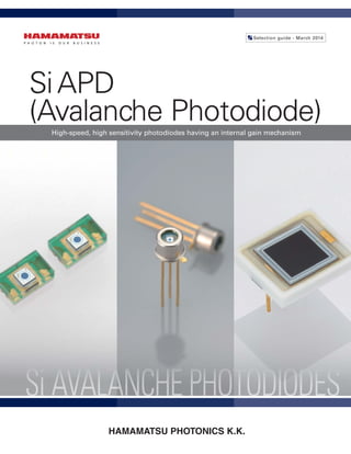
- 1. SiAPD (Avalanche Photodiode) Selection guide - March 2014 High-speed, high sensitivity photodiodes having an internal gain mechanism HAMAMATSU PHOTONICS K.K.
- 2. Contents S i A v a l a n c h e P h o t o d i o d e Short wavelength type Si APD · · · · · · · · · · · · · · · 5 · Low-bias operation· · · · · · · · · · · · · · · · · · · · · · · · · 5 · Low terminal capacitance · · · · · · · · · · · · · · · · · · · 6 Si APD High-speed, high sensitivity photodiodes having an internal gain mechanism
- 3. Near infrared type Si APD· · · · · · · · · · · · · · · · · · · 7 · Low bias operation· · · · · · · · · · · · · · · · · · · · · · · · · 7 · Low temperature coefficient· · · · · · · · · · · · · · · · · 9 · 900 nm band, low terminal capacitance · · · · · · 10 · 1000 nm band, high sensitivity · · · · · · · · · · · · · · 10 APD modules · · · · · · · · · · · · · · · · · · · · · · · · · · · · 11 · Standard type· · · · · · · · · · · · · · · · · · · · · · · · · · · · 11 · High-sensitivity type · · · · · · · · · · · · · · · · · · · · · · 12 · High-stability type · · · · · · · · · · · · · · · · · · · · · · · · 12 · High-speed type· · · · · · · · · · · · · · · · · · · · · · · · · · 13
- 4. 3 Si APD The photocurrent generation mechanism of the APD is the same as that of a normal photodiode. When light enters a photo- diode, electron-hole pairs are generated if the light energy is higher than the band gap energy. The ratio of the number of gener- ated electron-hole pairs to the number of incident photons is defined as the quantum efficiency (QE), expressed in percent (%). The mechanism by which carriers are generated inside an APD is the same as in a photodiode, but the APD is different from a photodiode in that it has a function to multiply the generated carriers. When electron-hole pairs are generated in the depletion layer of an APD with a reverse voltage applied to the PN junction, the electric field causes the electrons to drift toward the N+ side and the holes to drift toward the P+ side. The higher the electric field strength, the higher the drift speed of these carriers. However, when the electric field reaches a certain level, the carriers are more likely to collide with the crystal lattice so that the drift speed becomes saturated at a certain speed. If the electric field is increased even further, carriers that es- caped the collision with the crystal lattice will have a great deal of energy. When these carriers collide with the crystal lattice, a phenomenon takes place in which new electron-hole pairs are generated. This phenomenon is called ionization. These electron-hole pairs then create additional electron-hole pairs, which generate a chain reaction of ionization. Type Recommended wavelength (nm) Peak sensitivity wavelength (nm) Type no. Package Features Applications Short wavelength type Low-bias operation 200 to 650 620 S12053 series, etc. Metal Enhanced sensitivity in the UV to visible region · Low-light-level detection · Analytical instrumentsLow terminal capacitance 320 to 650 600 S8664-K series Metal S8664-55/-1010 Ceramic S8550-02 Near infrared type Low-bias operation 600 to 800 800 S12023 series, etc. Metal High sensitivity in the near IR region and low bias voltage (operating voltage) · FSO · Optical rangefinders · Optical fiber communication S10341 series Surface mount type Compact, thin, low cost · Optical rangefinders · Laser radars · FSO Low temperature coefficient 600 to 800 800 S12062 series, etc. Metal Low temperature coefficient of the bias voltage, easy gain adjustment · FSO · Optical rangefinders · Optical fiber communication 900 nm band, low terminal capacitance 800 to 1000 860 S12092 series, etc. Metal Enhanced sensitivity in the 900 nm band · Optical rangefinders · Laser radars 1000 nm band/ high sensitivity 900 to 1150 960 S11519 series Metal Enhanced sensitivity in the 1000 nm band, low bias voltage (operating voltage) · YAG laser detection, etc. Si APD The APD is a high-speed, high-sensitivity photodiode that internally multiplies photocurrent when reverse voltage is applied. The APD, having a signal multiplication function inside its element, achieves higher S/N than the PIN photodiode and can be used in a wide range of applications such as high-accuracy rangefinders and low-light-level detection that use scintillators. Though the APD can detect lower level light than the PIN photodiode, it does require special care and handling such as the need for higher reverse voltage and more detailed consideration of its temperature-dependent gain characteristics. Type Type no. Features Standard type C12702 series Contains near infrared type or short wavelength type APD. FC/SMA fiber adapters are also available. High-sensitivity type C12703 series High gain type for low-light-level detection High-stability type C10508-01 Digital temperature compensation type, high stability APD module High-speed type C5658 Can be used over a wide frequency range (up to 1 GHz) APD module Principle of avalanche multiplication Si APD (avalanche photodiode) Generated carriers produce new electron- hole pairs while being accelerated by high electric field. Ionization Newly generated carriers are also accelerated to produce further electron-hole pairs, and this process repeats itself. Avalanche multiplication Gain proportional to the applied reverse bias voltage can be obtained. - ---- + + + + - - - P + P - P High voltage N+ Avalanche layer Principle of APD operation KAPDC0006EC
- 5. Si APD 4 Wavelength (nm) Cutofffrequency(MHz) 200 0 200 400 600 800 1000 400 600 800 1000 1200 High Low Short wavelength type (Low-bias operation) Short wavelength type (Low terminal capacitance) Near infrared type Low-bias operation Low temperature coefficient ( ) Near infrared type (1000 nm band/high sensitivity) (photosensitive area size compared at 0.5 mm) Near infrared type 900 nm band, low terminal capacitance ( ) Response speed (Hz) DC 103 10 4 105 10 6 107 109 10 8 Sensitivity(V/W) 100 10 k10 1 k 100 k 1 M 10 M 100 M 1 G DC to 100 kHz -1.5 × 10⁸ V/W 50 kHz to 1 GHz 2.5 × 10⁵ V/W 4 types available for different photosensitive areas and wavelengths 4 kHz to 100 MHz -1 × 10⁴ V/W DC to 10 MHz 1.5 × 10⁶ V/W C12703-01 C12703 C5658 C12702 series DC to 10 MHz 2.5 × 10⁵ to 1.25 × 10⁷ V/W C10508-01 Wavelength (nm) Photosensitivity(A/W) 200 400 55 50 40 30 20 10 45 35 25 15 5 0 600 800 1000 1200 Near infrared type (Low-bias operation) Near infrared type (1000 nm band/high sensitivity) Near infrared type (Low temperature coefficient) Short wavelength type (Low-bias operation) Short wavelength type (Low terminal capacitance) (Typ. Ta=25 °C, M=50, λ=650 nm) Near infrared type (900 nm band, low terminal capacitance) KAPDB0196EC Cutoff frequency vs. recommended wavelength KAPDB0197EB Sensitivity vs. response speed (APD modules) KAPDB0195ED Spectral response (Si APD)
- 6. 5 Si APD Low-bias operation Type no. Effective*1 photosensitive area (mm) Spectral response range (nm) Breakdown voltage max. ID=100 μA (V) Temp. coefficient of breakdown voltage (V/°C) Cutoff*2 frequency RL=50 Ω (MHz) Rise*2 time RL=50 Ω (ns) Terminal*2 capacitance (pF) Gain λ=650 nm Package S12053-02 ϕ0.2 200 to 1000 200 0.14 900 0.4 2 50 TO-18S12053-05 ϕ0.5 400 0.9 5 S12053-10 ϕ1.0 250 1.5 15 S9075 ϕ1.5 100 3.5 30 TO-5 S5344 ϕ3.0 25 14 120 S5345 ϕ5.0 8 45 320 TO-8 *1: Area in which a typical gain can be obtained *2: Value obtained when operated at the gain indicated in the table 20 30 0 10 Photosensitivity(A/W) (Typ. Ta=25 °C, M at 650 nm) Wavelength (nm) 200 400 600 800300 500 700 900 1000 1100 M=10 M=20 M=50 0 20 40 60 80 100 Quantumefficiency(%) (Typ. Ta=25 °C) Wavelength (nm) 200 300 400 600 800 1000500 700 900 1100 Gain Reverse voltage (V) 103 102 101 100 (Typ. λ=650 nm) 130 160140 150 -20 °C 0 °C 20 °C 40 °C 60 °C These are short wavelength Si APDs with enhanced sensitivity in the UV to visible region. They offer high gain, high sensitivity, and low noise in the short wavelength region. They are suitable for applications such as low-light-level measurement and analytical instruments. KAPDB0010ED Spectral response KAPDB0023EB Quantum efficiency vs. wavelength KAPDB0011EC Gain vs. reverse voltage Short wavelength type Si APD
- 7. Si APD 6 Low terminal capacitance Type no. Effective*1 photosensitive area (mm) Spectral response range (nm) Breakdown voltage max. ID=100 μA (V) Temp. coefficient of breakdown voltage (V/°C) Cutoff*2 frequency RL=50 Ω (MHz) Rise*2 time RL=50 Ω (ns) Terminal*2 capacitance (pF) Gain λ=420 nm Package S8664-02K ϕ0.2 320 to 1000 500 0.78 700 0.5 0.8 50 TO-5 S8664-05K ϕ0.5 680 0.52 1.6 S8664-10K ϕ1.0 530 0.66 4 S8664-20K ϕ2.0 280 1.3 11 S8664-30K ϕ3.0 140 2.5 22 TO-8 S8664-50K ϕ5.0 60 6 55 S8664-55 5 × 5 40 9 80 Ceramic S8664-1010 10 × 10 11 32 270 Type no. Effective*1 photosensitive area (mm) Spectral response range (nm) Breakdown voltage max. (V) Temp. coefficient of breakdown voltage (V/°C) Cutoff*2 frequency RL=50 Ω (MHz) Terminal*2 capacitance (pF) Gain λ=420 nm Package S8550-02 1.6 × 1.6 (× 32 elements) 320 to 1000 500 0.78 250 10 (per element) 50 Ceramic *1: Area in which a typical gain can be obtained *2: Value obtained when operated at the gain indicated in the table KAPDB0073EC Spectral response KAPDB0125EA Quantum efficiency vs. wavelength KAPDB0076EB Gain vs. reverse voltage 4 × 8 element array 10 25 20 15 0 5 Photosensitivity(A/W) (Typ. M=50 at 420 nm) Wavelength (nm) 200 400 600 800 1000 1200 S8664-02K/-05K/-10K/ -20K/-30K/-50K S8664-55/-1010 S8550 40 100 80 60 0 20 Quantumefficiency(%) Wavelength (nm) 200 400 600 800 1000 1200 (Typ. Ta=25 °C) S8664-02K/-05K/-10K/ -20K/-30K/-50K S8664-55/-1010 S8550 1000 (Typ. λ=420 nm) 1 100 10 Gain Reverse voltage (V) 200 300 400 500 -20 °C 0 °C 20 °C 40 °C 60 °C Short wavelength type Si APD
- 8. 7 Si APD Type no. Effective*1 photosensitive area (mm) Spectral response range (nm) Breakdown voltage max. ID=100 μA (V) Temp. coefficient of breakdown voltage (V/°C) Cutoff*2 frequency RL=50 Ω (MHz) Terminal*2 capacitance (pF) Gain λ=800 nm Package S12023-02 ϕ0.2 400 to 1000 200 0.65 1000 1 100 TO-18 S12023-05 ϕ0.5 900 2S12051 S12086 S12023-10 ϕ1.0 600 6 S12023-10A S3884 ϕ1.5 400 10 TO-5 S2384 ϕ3.0 120 40 60 S2385 ϕ5.0 40 95 40 TO-8 Type no. Effective*1 photosensitive area (mm) Spectral response range (nm) Breakdown voltage max. (V) Temp. coefficient of breakdown voltage (V/°C) Cutoff*2 frequency RL=50 Ω (MHz) Terminal*2 capacitance (pF) Gain λ=800 nm Package S10341-02 ϕ0.2 400 to 1000 200 0.65 1000 1 100 Plastic S10341-05 ϕ0.5 900 2 *1: Area in which a typical gain can be obtained *2: Value obtained when operated at the gain indicated in the table Low-bias operation These are near infrared Si APDs that operate with low bias voltage. Since high gain can be attained with a bias voltage of 200 V or less, they are suitable for applications such as FSO, laser radar, and optical fiber communication. Surface mount type The S10341 series is a low cost, small size Si APD with a surface-mount plastic package suitable for mass production. Near infrared type Si APD
- 9. Si APD 8 Spectral response Quantum efficiency vs. wavelength Gain vs. reverse voltage Wavelength (nm) Photosensitivity(A/W) (Typ. Ta=25 °C, M at 800 nm) 200 400 600 800 1000300 500 700 900 1100 40 20 0 50 30 10 M=100 M=50 KAPDB0021EA Wavelength (nm) Quantumefficiency(%) 60 200 400 600 800 1000300 500 700 900 1100 40 20 0 80 100 (Typ. Ta=25 °C) 80 100 120 140 160 180 1 10 100 1000 10000 Reverse voltage (V) Gain (Typ. λ=800 nm) -20 °C 0 °C 20 °C 40 °C 60 °C KAPDB0020EB KAPDB0017EC Near infrared type Si APD
- 10. 9 Si APD Type no. Effective*1 photosensitive area (mm) Spectral response range (nm) Breakdown voltage max. ID=100 μA (V) Temp. coefficient of breakdown voltage (V/°C) Cutoff*2 frequency RL=50 Ω (MHz) Terminal*2 capacitance (pF) Gain λ=800 nm Package S12060-02 ϕ0.2 400 to 1000 300 0.4 1000 1 100 TO-18S12060-05 ϕ0.5 900 2.5 S12060-10 ϕ1.0 600 6 S6045-04 ϕ1.5 350 12 TO-5 S6045-05 ϕ3.0 80 50 60 S6045-06 ϕ5.0 35 120 40 TO-8 *1: Area in which a typical gain can be obtained *2: Value obtained when operated at the gain indicated in the table Low temperature coefficient These are near infrared Si APDs featuring low temperature coefficient of the bias voltage. They produce stable gain over a wide temperature range. They are suitable for applications such as FSO, laser radar, and optical fiber communication. Spectral response Quantum efficiency vs. wavelength Gain vs. reverse voltage KAPDB0026EA Wavelength (nm) Photosensitivity(A/W) (Typ. Ta=25 °C, M at 800 nm) 200 40 20 0 50 30 10 400 600 800 1000300 500 700 900 1100 M=100 M=50 KAPDB0029EB Reverse voltage (V) Gain (Typ. λ=800 nm) 160 200 220 240 102 100 101 260 104 103 180 -20 °C 0 °C 20 °C 40 °C 60 °C KAPDB0027EA Wavelength (nm) Quantumefficiency(%) (Typ. Ta=25 °C) 200 400 600 800 1000300 500 700 900 1100 40 20 0 80 60 100
- 11. Si APD 10 900 nm band, low terminal capacitance This series is used in laser radar and other applications. It features a gradual curve of gain versus reverse voltage curve, providing stable operation. Type no. Effective*1 photosensitive area (mm) Spectral response range (nm) Breakdown voltage max. ID=100 μA (V) Temp. coefficient of breakdown voltage (V/°C) Cutoff*2 frequency RL=50 Ω (MHz) Terminal*2 capacitance (pF) Gain λ=900 nm Package S12092-02 ϕ0.2 440 to 1100 350 1.85 400 0.4 100 TO-18 S12092-05 ϕ0.5 0.7 S9251-10 ϕ1.0 380 1.9 TO-5 S9251-15 ϕ1.5 350 3.6 *1: Area in which a typical gain can be obtained *2: Value obtained when operated at the gain indicated in the table 1000 nm band, high sensitivity The S11519 series incorporates MEMS technology to enhance the sensitivity in the near IR region forYAG laser (1.06 μm) detection. Type no. Effective photosensitive area (mm) Spectral response range (nm) Breakdown voltage max. ID=100 μA (V) Temp. coefficient of breakdown voltage (V/°C) Cutoff frequency RL=50 Ω (MHz) Terminal capacitance (pF) Gain λ=890 nm Package S11519-10 ϕ1.0 600 to 1150 500 1.7 400 2 100 TO-5 S11519-30 ϕ3.0 230 12 TO-8 Spectral response Gain vs. reverse voltage S9251 series S11519 series KAPDB0109EC Wavelength (nm) Photosensitivity(A/W) (Typ. Ta=25 °C, M=100 at 800 nm) 400 50 20 0 80 70 40 60 30 10 600 800 1000 1200 S9251 series S11519 series KAPDB0082EB Reverse voltage (V) (Typ. λ=800 nm) Gain 150 200 250100 1 101 102 103 104 300 -20 °C 20 °C0 °C 40 °C 60 °C KAPDB0185EA Reverse voltage (V) Gain 100 300 102 100 101 400 104 103 200 -20 °C 0 °C 20 °C 60 °C 40 °C (Typ.) Near infrared type Si APD
- 12. 11 Si APD Type no. Effective* photosensitive area (mm) Built-in APD Cutoff frequency Photoelectric conversion sensitivity M=30, λ=800 nm (V/W) Minimum detection limit M=30, λ=800 nm (nW rms) Temperature stability of gain 25 ± 10 °C (%) Supply voltage (V) Low High C12702-03 ϕ1.0 S12023-10 4 kHz 100 MHz -6.8 × 10⁴ 3 ±2.5 +5 C12702-04 ϕ3.0 S2384 80 MHz -2.3 × 10⁴ 3.6 Short wavelength type Features Peak sensitivity wavelength: 620 nm Wide bandwidth Optical fiber adapters are also available (sold separately). Applications Si APD evaluation Film scanners Laser monitoring Type no. Effective* photosensitive area (mm) Built-in APD Cutoff frequency Photoelectric conversion sensitivity M=30, λ=620 nm (V/W) Minimum detection limit M=30, λ=620 nm (nW rms) Temperature stability of gain 25 ± 10 °C (%) Supply voltage (V) Low High C12702-11 ϕ1.0 S12053-10 4 kHz 100 MHz -2.5 × 10⁴ 5 ±2.5 +5 C12702-12 ϕ3.0 S5344 40 MHz -1.9 × 10⁴ 6.3 * Area in which a typical gain can be obtained Standard type Near infrared type Features Peak sensitivity wavelength: 800 nm Wide bandwidth Optical fiber adapters are also available (sold separately). Applications Si APD evaluation FSO Barcode readers Laser radars Optical rangefinders Optical communication The APD module consists of an amplifier and bias power supply assembled in a compact form to facilitate the use of the Si APD. Running on a +5 V power supply, it can be used for a variety of light detection applications up to 100 MHz of frequency bandwidth. APD modules
- 13. Si APD 12 Type no. Effective* photosensitive size (mm) Internal APD Cutoff frequency Photoelectric conversion sensitivity M=30, λ=800 nm (V/W) Minimum detection limit M=30, λ=800 nm (pW rms) Temperature stability of gain 25 ± 10 °C (%) Supply voltage (V) Low High C12703 ϕ1.5 S3884 DC 10 MHz 1.50 × 10⁶ 630 ±2.5 ±12 C12703-01 ϕ3.0 S2384 100 kHz -1.50 × 10⁸ 6.3 High-sensitivity type Features Low-light-level detection DC light detection High gain Applications Si APD evaluation Fluorescence measurement Barcode readers Particle counters Film scanners These are high-gain APD modules suitable for low-light-level detection. They can be used for DC light detection. High-stability type The C10508-01 consists of an APD, current-voltage converter, high-voltage power supply circuit as well as a microcontroller for adjusting the APD gain and controlling temperature compensation with high accuracy. This makes it easy to adjust the APD gain and even at high gain, stable detection is possible even under temperature fluctuating conditions. Type no. Effective* photosensitive size (mm) Internal APD Cutoff frequency Photoelectric conversion sensitivity M=250, λ=800 nm (V/W) Minimum detection limit M=250, λ=800 nm (pW rms) Temperature stability of gain 0 to 40 °C (%) Supply voltage (V) Low High C10508-01 ϕ1.0 S12023-10 DC 10 MHz 1.25 × 10⁷ 63 ±5.0 max. ±5 * Area in which a typical gain can be obtained. Features Gain: adjustable by switch or PC command Gain temperature stability: ±5% or less (Gain=250, Ta=0 °C to +40 °C) Easy handling: only ±5 V power supply Applications Si APD evaluation Power meters Low-light-level detection FC/SMA fiber adapter (sold separately) APD module FC fiber adapter SMA fiber adapter C12702-03 A8407-18 A8424-18 C12702-04 A8407-05A A8424-05A C12702-11 A8407-18 A8424-18 C12702-12 A8407-05A A8424-05A C12703 A8407-05 A8424-05 C12703-01 A8407-05A A8424-05A C10508-01 A12855-01 A12855-02 FC or SMA fiber adapters can be attached to the following APD modules to allow FC or SMA optical fiber cables to be connected to the modules. APD modules
- 14. 13 Si APD Type no. Effective*1 photosensitive size (mm) Internal APD Cutoff frequency Photoelectric conversion sensitivity M=100, λ=800 nm (V/W) Minimum detection limit M=100, λ=800 nm (nW rms) Temperature stability of gain 25 ± 10 °C (%) Supply voltage (V) Low High C5658 ϕ0.5 S12023-05 50 kHz 1 GHz 2.50 × 10⁵ 16 ±5.0 +12 High-speed type Features High-speed light detection Flat frequency characteristics Compact and lightweight Single power supply operation Applications OTDR Optical communication Laser radars FSO Optical rangefinders This device can be used in a wide frequency range (up to 1 GHz).
- 15. Copies of the full warranty can be obtained prior to the purchase of products by contacting your local Hamamatsu sales office. Hamamatsu makes no other warranties, and any and all implied warranties of merchantability, or fitness for a particular purpose, are hereby disclaimed. The customer is responsible for use of the product in accordance with Hamamatsu's instructions and within the operating specifications and ratings listed in this catalogue. Hamamatsu shall not be responsible for the customer's improper selection of a product for a particular application or otherwise. No warranty will apply if the products are in any way altered or modified after delivery by Hamamatsu or for any intentional misuse or abuse of the products. Proper design safety rules should be followed when incorporating these products into devices that could potentially cause bodily injury. Hamamatsu's liability on any claim for loss or damage arising out of the supplying of any products, whether based on contract, warranty, tort (including negligence and for property damage or death and bodily injury) or other grounds, shall not in any event exceed the price allocable to such products or a part thereof involved in the claim, regardless of cause or fault. In no event shall Hamamatsu be responsible to the customer or any third party for any consequential, incidental or indirect damages, including but not limited to loss of profits, revenues, sales, data, business, goodwill or use, even if the company has been advised of the possibility of such loss or damage. The limitation of liability set forth herein applies both to products and services purchased or otherwise provided hereunder. This warranty is limited to repair or replacement, at the sole option of Hamamatsu, of any product which is defective in workmanship or materials used in manufacture. All warranty claims must be made within 1 year from the date of purchase or provision of the products or services. Products that are amenable to repair shall be done so either under warranty or pursuant to a separate repair agreement. Some products cannot be repaired either because of the nature or age of the product, the unavailability of spare parts, or the extent of the damage is too great. Please contact your local Hamamatsu office for more details. The products described in this catalogue should be used by persons who are accustomed to the properties of photoelectronics devices, and have expertise in handling and operating them. They should not be used by persons who are not experienced or trained in the necessary precautions surrounding their use. The information in this catalogue is subject to change without prior notice. Information furnished by Hamamatsu is believed to be reliable. However, no responsibility is assumed for possible inaccuracies or omissions. Before using these products, always contact us for the delivery specification sheet to check the latest specifications. No patent rights are granted to any of the circuits described herein.
- 16. Cat. No. KAPD0001E05 Mar. 2014 DN Printed in Japan (2,000) Main Products Si photodiodes APD Photo IC Image sensors X-ray flat panel sensors PSD Infrared detectors LED Optical communication devices Automotive devices Mini-spectrometers High energy particle/X-ray detectors Opto-semiconductor modules Hamamatsu also supplies: Photoelectric tubes Imaging tubes Light sources Imaging and processing systems Information in this catalogue is believed to be reliable. However, no responsibility is assumed for possible inaccuracies or omissions. Specifications are subject to change without notice. No patent rights are granted to any of the circuits described herein. © 2014 Hamamatsu Photonics K.K. Quality, technology, and service are part of every product. HAMAMATSU PHOTONICS K.K., Solid State Division 1126-1, Ichino-cho, Higashi-ku, Hamamatsu City, 435-8558, Japan Telephone: (81)53-434-3311, Fax: (81)53-434-5184 www.hamamatsu.com JAPAN: HAMAMATSU PHOTONICS K.K. 325-6, Sunayama-cho, Naka-ku Hamamatsu City, 430-8587, Japan Telephone: (81)53-452-2141, Fax: (81)53-456-7889 China: HAMAMATSU PHOTONICS (CHINA) CO., LTD. 1201 Tower B, Jiaming Center, No.27 Dongsanhuan Beilu, Chaoyang District, Beijing 100020, China Telephone: (86)10-6586-6006, Fax: (86)10-6586-2866 E-mail: hpc@hamamatsu.com.cn U.S.A.: HAMAMATSU CORPORATION Main Office 360 Foothill Road, P.O. BOX 6910, Bridgewater, N.J. 08807-0910, U.S.A. Telephone: (1)908-231-0960, Fax: (1)908-231-1218 E-mail: usa@hamamatsu.com Western U.S.A. Office: Suite 200, 2875 Moorpark Avenue San Jose, CA 95128, U.S.A. Telephone: (1)408-261-2022, Fax: (1)408-261-2522 E-mail: usa@hamamatsu.com United Kingdom, South Africa: HAMAMATSU PHOTONICS UK LIMITED Main Office 2 Howard Court, 10 Tewin Road, Welwyn Garden City, Hertfordshire AL7 1BW, United Kingdom Telephone: (44)1707-294888, Fax: (44)1707-325777 E-mail: info@hamamatsu.co.uk South Africa office: PO Box 1112 Buccleuch 2066 Johannesburg, South Africa Telephone/Fax: (27)11-802-5505 France, Portugal, Belgium, Switzerland, Spain: HAMAMATSU PHOTONICS FRANCE S.A.R.L. 19, Rue du Saule Trapu, Parc du Moulin de Massy, 91882 Massy Cedex, France Telephone: (33)1 69 53 71 00 Fax: (33)1 69 53 71 10 E-mail: infos@hamamatsu.fr Swiss Office: Dornacherplatz 7 4500 Solothurn, Switzerland Telephone: (41)32/625 60 60, Fax: (41)32/625 60 61 E-mail: swiss@hamamatsu.ch Belgium Office: Axisparc Technology , rue Andre Dumont 7 - 1435 Mont-Saint-Guibert, Belgium Telephone: (32)10 45 63 34 Fax: (32)10 45 63 67 E-mail: infoweb@hamamatsu.be Spanish Office: C. Argenters, 4 edif 2 Parque Tecnologico del Valles E-08290 CERDANYOLA, (Barcelona) Spain Telephone: (34)93 582 44 30 Fax: (34)93 582 44 31 E-mail: infospain@hamamatsu.es Germany, Denmark, Netherlands, Poland: HAMAMATSU PHOTONICS DEUTSCHLAND GmbH Arzbergerstr. 10, D-82211 Herrsching am Ammersee, Germany Telephone: (49)8152-375-0, Fax: (49)8152-265-8 E-mail: info@hamamatsu.de Danish Office: Lautruphoj 1-3 DK-2750 Ballerup, Denmark Telephone: (45)70 20 93 69, Fax: (45)44 20 99 10 E-mail: info@hamamatsu.de Netherlands Office: Televisieweg 2 NL-1322 AC Almere, The Netherlands Telephone: (31)36-5405384, Fax: (31)36-5244948 E-mail: info@hamamatsu.nl Poland Office: 02-525 Warsaw, 8 St. A. Boboli Str., Poland Telephone: (48)22-646-0016, Fax: (48)22-646-0018 E-mail: jbaszak@hamamatsu.de North Europe and CIS: HAMAMATSU PHOTONICS NORDEN AB Main Office Torshamnsgatan 35 16440 Kista, Sweden Telephone: (46)8-509-031-00, Fax: (46)8-509-031-01 E-mail: info@hamamatsu.se Russian Office: 11, Chistoprudny Boulevard, Building 1, 101000, Moscow, Russia Telephone: (7) 495 258 85 18, Fax: (7) 495 258 85 19 E-mail: info@hamamatsu.ru Italy: HAMAMATSU PHOTONICS ITALIA S.R.L. Strada della Moia, 1 int. 6 20020 Arese, (Milano), Italy Telephone: (39)02-935 81 733 Fax: (39)02-935 81 741 E-mail: info@hamamatsu.it Rome Office: Viale Cesare Pavese, 435 00144 Roma, Italy Telephone: (39)06-50513454, Fax: (39)06-50513460 E-mail: inforoma@hamamatsu.it Taiwan: HAKUTO TAIWAN LTD. 6F, No.308, Pa teh Road, Sec, 2, Taipei, Taiwan R.O.C. Telephone: (886)2-8772-8910 Fax: (886)2-8772-8918 KORYO ELECTRONICS CO., LTD. 9F-7, No.79, Hsin Tai Wu Road Sec.1, Hsi-Chih, Taipei, Taiwan, R.O.C. Telephone: (886)2-2698-1143, Fax: (886)2-2698-1147 Republic of Korea: SANGKI CORPORATION Suite 431, World Vision BLDG. 24-2 Yoido-Dong Youngdeungpo-Ku Seoul, 150-877 Telephone: (82)2-780-8515 Fax: (82)2-784-6062 Singapore: HAKUTO SINGAPORE PTE LTD. Block 2, Kaki Bukit Avenue 1, #04-01 to #04-04 Kaki Bukit Industrial Estate, Singapore 417938 Telephone: (65)67458910, Fax: (65)67418200 Sales Offices