SlideShare une entreprise Scribd logo
1  sur  24
1
Objective:- A Comparative Study of Working principle and Applications of various Non-
Conventional machining Processes.
1. Introduction
Non-traditional manufacturing processes is defined as a group of processes that remove excess
material by various techniques involving Mechanical, Thermal, Electrical or Chemical energy
or combinations of these energies but do not use a sharp cutting tools as it needs to be used for
traditional manufacturing processes.
Extremely hard and brittle materials are difficult to machine by traditional machining processes
such as turning, drilling, shaping and milling. Non-traditional machining processes, also called
advanced manufacturing processes, are employed where traditional machining processes are
not feasible, satisfactory or economical due to special reasons as outlined below.
• Very hard fragile materials difficult to clamp for traditional machining
• When the work piece is too flexible or slender
• When the shape of the part is too complex
Several types of non-traditional machining processes have been developed to meet extra
required machining conditions. When these processes are employed properly, they offer many
advantages over non-traditional machining processes.
2. Material removal processes can be divided into two groups
1. Conventional Machining Processes
2. Unconventional Machining processes or Non-Traditional Manufacturing Processes
Conventional Machining Processes mostly remove material in the form of chips by applying
forces on the work material with a wedge shaped cutting tool that is harder than the work
material under machining condition.
The major characteristics of conventional machining are:
• Generally macroscopic chip formation by shear deformation.
• Material removal takes place due to application of cutting forces – energy domain can be
classified as mechanical.
• Cutting tool is harder than work piece at room temperature as well as under machining
conditions.
Non-conventional manufacturing processes is defined as a group of processes that remove
excess material by various techniques involving Mechanical, Thermal, Electrical or Chemical
energy or combinations of these energies but do not use a sharp cutting tools as it needs to be
used for traditional manufacturing processes.
2
Material removal may occur with chip formation or even no chip formation may take place.
For example in AJM, chips are of microscopic size and in case of Electrochemical machining
material removal occurs due to electrochemical dissolution at atomic level.
2. NEED FOR UNCONVENTIONAL MACHINING PROCESSES
i. Extremely hard and brittle materials or Difficult to machine material are difficult to
machine by traditional machining processes.
ii. When the workpiece is too flexible or slender to support the cutting or grinding forces.
When the shape of the part is too complex.
4. CLASSIFICATION OF NON-CONVENTIONAL MACHINING PROCESSES:
A. Mechanical Processes B. Electrochemical Processes
i. Abrasive Jet Machining (AJM) i. Electrochemical Machining (ECM)
ii. Ultrasonic Machining (USM) ii. Electro Chemical Grinding (ECG)
iii. Water Jet Machining (WJM) iii. Electro Jet Drilling (EJD)
iv. Abrasive Water Jet Machining (AWJM)
C. Electro-Thermal Processes D. Chemical Processes
i. Electro-discharge machining (EDM) i. Chemical Milling (CHM)
ii. Laser Jet Machining (LJM) ii. Photochemical Milling (PCM)
iii. Electron Beam Machining (EBM)
 MECHANICAL PROCESSES
1. ABRASIVE JET MACHINING (AJM)
In Abrasive Jet Machining (AJM), abrasive particles are made to impinge on the work material
at a high velocity. The jet of abrasive particles is carried by carrier gas or air. The high velocity
stream of abrasive is generated by converting the pressure energy of the carrier gas or air to its
kinetic energy and hence high velocity jet. The nozzle directs the abrasive jet in a controlled
manner onto the work material, so that the distance between the nozzle and the work piece and
the impingement angle can be set desirably. The high velocity abrasive particles remove the
material by micro-cutting action as well as brittle fracture of the work material. Fig. 1.1
schematically shows the material removal process.
3
Fig 1: AJM
In AJM, generally, the abrasive particles of around 50 μm grit size would impinge on the work
material at velocity of 200 m/s from a nozzle of I.D. of 0.5 mm with a standoff distance of
around 2 mm. The kinetic energy of the abrasive particles would be sufficient to provide
material removal due to brittle fracture of the work piece or even micro cutting by the abrasives.
Working
In AJM, air is compressed in an air compressor and compressed air at a pressure of around 5
bar is used as the carrier gas as shown in Fig. 1.2. Fig. 1.2 Also shows the other major parts of
the AJM system. Gases like CO2, N2 can also be used as carrier gas which may directly be
issued from a gas cylinder. Generally oxygen is not used as a carrier gas.
Fig 2: AJM System
The carrier gas is first passed through a pressure regulator to obtain the desired working
pressure. The gas is then passed through an air dryer to remove any residual water vapour. To
4
remove any oil vapour or particulate contaminant the same is passed through a series of filters.
Then the carrier gas enters a closed chamber known as the mixing chamber. The abrasive
particles enter the chamber from a hopper through a metallic sieve. The sieve is constantly
vibrated by an electromagnetic shaker. The mass flow rate of abrasive (15 gm/min) entering
the chamber depends on the amplitude of vibration of the sieve and its frequency. The abrasive
particles are then carried by the carrier gas to the machining chamber via an electro- magnetic
on-off valve. The machining enclosure is essential to contain the abrasive and machined
particles in a safe and eco-friendly manner. The machining is carried out as high velocity (200
m/s) abrasive particles are issued from the nozzle onto a work piece traversing under the jet.
 Process Parameters and Machining Characteristics
Abrasive: Material - Al2O3 / SiC / Glass
beads
Shape –Irregular / spherical
Size – 10~50 μm
Mass flow rate – 2 ~ 20 gm/min
Carrier gas: Composition – Air, CO 2, N 2
Density – Air ~ 1.3 kg/m3
Velocity – 500 ~ 700 m/s
Pressure – 2 ~ 10 bar
Flow rate – 5 ~ 30 lpm
Abrasive Jet: Velocity – 100 ~ 300 m/s
Mixing ratio – mass flow ratio of abrasive
to gas
Stand-off distance – 0.5 ~ 5 mm
Impingement Angle – 60 0 ~ 90 0
Nozzle: Material – WC
Diameter – (Internal) 0.2 ~ 0.8 mm
Life – 10 ~ 300 hours
The important machining characteristics in AJM are:
• The material removal rate (MRR) mm3/min or gm/min
• The machining accuracy
• The life of the nozzle
 Applications
• For drilling holes of intricate shapes in hard and brittle materials
• For machining fragile, brittle and heat sensitive materials
• AJM can be used for drilling, cutting, deburring, cleaning and etching.
• Micro-machining of brittle materials
 Limitations
• MRR is rather low (around ~ 15 mm3/min for machining glass)
• Abrasive particles tend to get embedded particularly if the work material is ductile
• Tapering occurs due to flaring of the jet
• Environmental load is rather high.
5
Fig 3: Effect of process parameters MRR
2. ABRASIVE WATER-JET MACHINING (AWJM)
Abrasive water jet cutting is an extended version of water jet cutting; in which the water jet
contains abrasive particles such as silicon carbide or aluminium oxide in order to increase the
material removal rate above that of water jet machining. Almost any type of material ranging
from hard brittle materials such as ceramics, metals and glass to extremely soft materials such
as foam and rubbers can be cut by abrasive water jet cutting. The narrow cutting stream and
computer controlled movement enables this process to produce parts accurately and efficiently.
This machining process is especially ideal for cutting materials that cannot be cut by laser or
thermal cut. Metallic, non-metallic and advanced composite materials of various thicknesses
can be cut by this process. This process is particularly suitable for heat sensitive materials that
cannot be machined by processes that produce heat while machining.
The schematic of abrasive water jet cutting is shown in Figure 15 which is similar to water jet
cutting apart from some more features underneath the jewel; namely abrasive, guard and
mixing tube. In this process, high velocity water exiting the jewel creates a vacuum which
sucks abrasive from the abrasive line, which mixes with the water in the mixing tube to form a
high velocity beam of abrasives.
6
Applications
Abrasive water jet cutting is highly used in aerospace, automotive and electronics industries.
In aerospace industries, parts such as
titanium bodies for military aircrafts, engine
components (aluminium, titanium, heat
resistant alloys), aluminium body parts and
interior cabin parts are made using abrasive
water jet cutting.
In automotive industries, parts like interior
trim (head liners, trunk liners, door panels)
and fibre glass body components and
bumpers are made by this process. Similarly,
in electronics industries, circuit boards and
cable stripping are made by abrasive water
jet cutting. Fig 4: AWJ Machining
Advantages of abrasive water jet cutting
• In most of the cases, no secondary
finishing required
• No cutter induced distortion
• Low cutting forces on workpieces
• Limited tooling requirements
• Little to no cutting burr
• Typical finish 125-250 microns
• Smaller kerf size reduces material
wastages
• No heat affected zone
• Localises structural changes
• No cutter induced metal contamination
• Eliminates thermal distortion
• No slag or cutting dross
• Precise, multi plane cutting of contours,
shapes, and bevels of any angle.
Limitations of abrasive water jet cutting
• Cannot drill flat bottom
• Cannot cut materials that degrades quickly with moisture
• Surface finish degrades at higher cut speeds which are frequently used for rough cut
The major disadvantages of abrasive water jet cutting are high capital cost and high noise levels
during operation.
7
3. Ultrasonic Machining (USM)
USM is mechanical material removal process or an abrasive process used to erode holes or
cavities on hard or brittle workpiece by using shaped tools, high frequency mechanical motion
and an abrasive slurry. USM offers a solution to the expanding need for machining brittle
materials such as single crystals, glasses and polycrystalline ceramics, and increasing complex
operations to provide intricate shapes and workpiece profiles. It is therefore used extensively
in machining hard and brittle materials that are difficult to machine by traditional
manufacturing processes. The hard particles in slurry are accelerated toward the surface of the
workpiece by a tool oscillating at a frequency up to 100 KHz - through repeated abrasions, the
tool machines a cavity of a cross section identical to its own. A schematic representation of
USM is shown in Figure.
Fig 5: USM Machining Operation
In ultrasonic machining, a tool of desired shape vibrates at an ultrasonic frequency (19 ~ 25
kHz) with an amplitude of around 15 – 50 μm over the workpiece. Generally the tool is pressed
downward with a feed force, F. Between the tool and workpiece, the machining zone is flooded
with hard abrasive particles generally in the form of a water based slurry. As the tool vibrates
over the workpiece, the abrasive particles act as the indenters and indent both the work material
and the tool. The abrasive particles, as they indent, the work material, would remove the same,
particularly if the work material is brittle, due to crack initiation, propagation and brittle
fracture of the material. Hence, USM is mainly used for machining brittle materials {which are
poor conductors of electricity and thus cannot be processed by Electrochemical and Electro-
discharge machining (ECM and ED)}.
USM is primarily targeted for the machining of hard and brittle materials (dielectric or
conductive) such as boron carbide, ceramics, titanium carbides, rubies, quartz etc. USM is a
versatile machining process as far as properties of materials are concerned. This process is able
to effectively machine all materials whether they are electrically conductive or insulator.
8
WORKING
The basic mechanical structure of an USM is very similar to a drill press. However, it has
additional features to carry out USM of brittle work material. The workpiece is mounted on a
vice, which can be located at the desired position under the tool using a 2 axis table. The table
can further be lowered or raised to accommodate work of different thickness. The typical
elements of an USM are,
1. Slurry delivery and return system
2. Feed mechanism to provide a
downward feed force on the tool
during machining
3. The transducer, which generates the
ultrasonic vibration
4. The horn or concentrator, which
mechanically amplifies the vibration
to the required amplitude of 15 – 50
μm and accommodates the tool at its tip. Fig 6: Schematic view of an Ultrasonic Machine
The ultrasonic vibrations are produced by the transducer. The transducer is driven by suitable
signal generator followed by power amplifier. The transducer for USM works on the following
principle
1. Piezoelectric effect 3. Magnetostrictive effect
2. Electrostrictive effect
Magnetostrictive transducers are most popular and robust amongst all. Fig. 7 shows a typical
magnetostrictive transducer along with horn. The horn or concentrator is a wave-guide, which
amplifies and concentrates the vibration to the tool from the transducer.
Fig 7: Working of horn as Mechanical amplifier of amplitude of vibration
9
The horn or concentrator can be of different shape like
Fig 8: Different Horns used in USM
Process Parameters and their Effects.
During discussion and analysis as presented in the previous section, the process parameters
which govern the ultrasonic machining process have been identified and the same are listed
below along with material parameters
• Amplitude of vibration (ao) – 15 – 50 μm
• Frequency of vibration (f) – 19 – 25 kHz
• Feed force (F) – related to tool dimensions
• Feed pressure (p)
• Abrasive size – 15 μm – 150 μm
• Abrasive material – Al2O3, SiC, B4C,
Boronsilicarbide, Diamond
• Flow strength of work material
• Flow strength of the tool material
• Contact area of the tool – A
• Volume concentration of abrasive in water
slurry – C
• The machining tool must be selected to be
highly wear resistant, such as high-carbon
steels.
The abrasives (25-60 µm in dia.) in the (water-based, up to 40% solid volume) slurry includes:
Boron carbide, silicon carbide and aluminum oxide.
Applications
 Used for machining hard and brittle metallic alloys, semiconductors, glass, ceramics,
carbides.
 Used for machining round, square, irregular shaped holes and surface impressions.
 Machining, wire drawing, punching or small blanking dies.
10
Fig 9: Effect of machining parameters on MRR
Advantage of USM
USM process is a non-thermal, non-chemical, creates no changes in the microstructures,
chemical or physical properties of the workpiece and offers virtually stress free machined
surfaces.
• Any materials can be machined regardless of their electrical conductivity
• Especially suitable for machining of brittle materials
• Machined parts by USM possess better surface finish and higher structural integrity.
• USM does not produce thermal, electrical and chemical abnormal surface
Some disadvantages of USM
• USM has higher power consumption and lower material-removal rates than traditional
fabrication processes.
11
• Tool wears fast in USM.
• Machining area and depth is restraint in USM.
 ELECTRICAL ENERGY BASED PROCESSES
1. Electrical discharge machining (EDM)
Electrical discharge machining is one of the most widely used non-traditional machining
processes. The main attraction of EDM over traditional machining processes such as metal
cutting using different tools and grinding is that this technique utilises thermoelectric process
to erode undesired materials from the workpiece by a series of discrete electrical sparks
between the workpiece and the electrode. A picture of EDM machine in operation.
The traditional machining processes rely on harder tool or abrasive material to remove the
softer material whereas non-traditional machining processes such as EDM uses electrical spark
or thermal energy to erode unwanted material in order to create desired shape. So, the hardness
of the material is no longer a dominating factor for EDM process. A schematic of an EDM
process is shown in Figure 2, where the tool and the workpiece are immersed in a dielectric
fluid.
EDM removes material by discharging an electrical current, normally stored in a capacitor
bank, across a small gap between the tool (cathode) and the workpiece (anode) typically in
order.
Fig 10: Working of EDM
Working principle of EDM
As shown in Figure 1, at the beginning of EDM operation, a high voltage is applied across the
narrow gap between the electrode and the workpiece. This high voltage induces an electric
field in the insulating dielectric that is present in narrow gap between electrode and workpiece.
12
This cause conducting particles suspended in the dielectric to concentrate at the points of
strongest electrical field. When the potential difference between the electrode and the
workpiece is sufficiently high, the dielectric breaks down and a transient spark discharges
through the dielectric fluid, removing small amount of material from the workpiece surface.
The volume of the material removed per spark discharge is typically in the range of 10-6 to 10-
6 mm3.
The material removal rate, MRR, in EDM is calculated by the following foumula:
MRR = 40 I / Tm 1.23 (cm3/min)
Where, I is the current amp, Tm is the melting temperature of workpiece in 0C.
Process Parameters
The process parameters in EDM are mainly related to the waveform characteristics. Fig. 11
shows a general waveform used in EDM.
Fig 11: Waveform used in EDM
The waveform is characterised by the
• The open circuit voltage - Vo
• The working voltage - Vw
• The maximum current - Io
• The pulse on time – the duration for which the voltage pulse is applied - ton
• The pulse off time – toff
13
• The gap between the workpiece and the tool – spark gap - δ
• The polarity – straight polarity – tool (-ve)
• The dielectric medium
• External flushing through the spark gap
Application of EDM
The EDM process has the ability to machine hard, difficult-to-machine materials. Parts with
complex, precise and irregular shapes for forging, press tools, extrusion dies, difficult internal
shapes for aerospace and medical applications can be made by EDM process.
Advantages of EDM
The main advantages of DM are:
• By this process, materials of any hardness can be machined;
• No burrs are left in machined surface;
• One of the main advantages of this process is that thin and fragile/brittle components can
be machined without distortion;
Limitations of EDM
The main limitations of this process are:
• This process can only be employed in electrically conductive materials;
• Material removal rate is low and the process overall is slow compared to conventional
machining processes;
• Unwanted erosion and over cutting of material can occur;
• Rough surface finish when at high rates of material removal.
Dielectric fluids
Dielectric fluids used in EDM process are hydrocarbon oils, kerosene and deionised water. The
functions of the dielectric fluid are to:
• Act as an insulator between the tool and the workpiece.
• Act as coolant.
• Act as a flushing medium for the removal of the chips.
The electrodes for EDM process usually are made of graphite, brass, copper and copper-
tungsten alloys.
Design considerations for EDM process are as follows:
• Deep slots and narrow openings should be avoided.
• The surface smoothness value should not be specified too fine.
• Rough cut should be done by other machining process. Only finishing operation should be
done in this process as MRR for this process is low.
14
 CHEMICAL AND ELECTRO CHEMICAL ENERGY BASED PROCESSES
1. Electrochemical Machining (ECM)
Electrochemical machining (ECM) is a metal-removal process based on the principle of reverse
electroplating. In this process, particles travel from the anodic material (workpiece) toward the
cathodic material (machining tool). A current of electrolyte fluid carries away the deplated
material before it has a chance to reach the machining tool. The cavity produced is the female
mating image of the tool shape.
Similar to EDM, the workpiece hardness is not a factor, making ECM suitable for machining
difficult-to –machine materials. Difficult shapes can be made by this process on materials
regardless of their hardness. A schematic representation of ECM process is shown in Figure 8.
The ECM tool is positioned very close to the workpiece and a low voltage, high amperage DC
current is passed between the workpiece and electrode. Some of the shapes made by ECM
process is shown in Figure 9.
Fig 12: Principle of Electro Chemical Machining (ECM)
PROCESS
During ECM, there will be reactions occurring at the electrodes i.e. at the anode or workpiece
and at the cathode or the tool along with within the electrolyte. Let us take an example of
machining of low carbon steel which is primarily a ferrous alloy mainly containing iron. For
electrochemical machining of steel, generally a neutral salt solution of sodium chloride (NaCl)
is taken as the electrolyte. The electrolyte and water undergoes ionic dissociation as shown
below as potential difference is applied
NaCl ↔ Na+ + Cl-
H2O ↔ H + + (OH)
As the potential difference is applied between the work piece (anode) and the tool (cathode),
the positive ions move towards the tool and negative ions move towards the workpiece. Thus
15
the hydrogen ions will take away electrons from the cathode (tool) and from hydrogen gas as:
2H + + 2e- = H2↑ at cathode.
Fig 13: Schematic representation of electro-chemical reactions
Similarly, the iron atoms will come out of the anode (work piece) as: Fe = Fe+ + + 2e
Within the electrolyte iron ions would combine with chloride ions to form iron chloride and
similarly sodium ions would combine with hydroxyl ions to form sodium hydroxide
Na + + OH- = NaOH
In practice FeCl2 and Fe(OH)2 would form and get precipitated in the form of sludge. In this
manner it can be noted that the work piece gets gradually machined and gets precipitated as the
sludge. Moreover there is not coating on the tool, only hydrogen gas evolves at the tool or
cathode. Fig. 2 depicts the electro-chemical reactions schematically. As the material removal
takes place due to atomic level dissociation, the machined surface is of excellent surface finish
and stress free.
The voltage is required to be applied for the electrochemical reaction to proceed at a steady
state. That voltage or potential difference is around 2 to 30 V. The applied potential difference,
however, also overcomes the following resistances or potential drops.
They are:
• The electrode potential
• The activation over potential
• Ohmic potential drop
• Concentration over potential
• Ohmic resistance of electrolyte
EQUIPMENT
The electrochemical machining system has the following modules:
• Power supply
• Electrolyte filtration and delivery system
• Tool feed system
• Working tank
Fig. 4 schematically shows an electrochemical drilling unit.
16
Fig 14: Schematic diagram of an electrochemical drilling unit
Advantages of ECM
• The components are not subject to either thermal or mechanical stress.
• No tool wear during ECM process.
• Fragile parts can be machined easily as there is no stress involved.
• ECM deburring can debur difficult to access areas of parts.
• High surface finish (up to 25 µm in) can be achieved by ECM process.
• Complex geometrical shapes in high-strength materials particularly in the aerospace industry
for the mass production of turbine blades, jet-engine parts and nozzles can be machined
repeatedly and accurately.
• Deep holes can be made by this process.
Limitations of ECM
• ECM is not suitable to produce sharp square corners or flat bottoms because of the tendency
for the electrolyte to erode away sharp profiles.
• ECM can be applied to most metals but, due to the high equipment costs, is usually used
primarily for highly specialized applications.
Material removal rate, MRR, in ECM
MRR = C .I. h (cm3/min)
17
C: specific (material) removal rate (e.g., 0.2052 cm3/amp-min for nickel);
I: current (amp);
h: current efficiency (90–100%).
The rates at which metal can electrochemically remove are in proportion to the current passed
through the electrolyte and the elapsed time for that operation. Many factors other than current
influence the rate of machining. These involve electrolyte type, rate of electrolyte flow, and
some other process conditions.
APPLICATION
Fig 14: Different applications of Electro Chemical Machining
 THERMAL ENERGY BASED PROCESSES
1. Laser–Beam Machining (LBM)
Laser-beam machining is a thermal material-removal process that utilizes a high-energy,
coherent light beam to melt and vaporize particles on the surface of metallic and non-metallic
workpieces. Lasers can be used to cut, drill, weld and mark. LBM is particularly suitable for
making accurately placed holes. A schematic of laser beam machining is shown in Figure.
18
Fig 15: LBM
Different types of lasers are available for manufacturing operations which are as follows:
• CO2 (pulsed or continuous wave): It is a gas laser that emits light in the infrared region. It
can provide up to 25 kW in continuous-wave mode.
• Nd:YAG: Neodymium-doped Yttrium-Aluminum-Garnet (Y3Al 5O12) laser is a solid- state
laser which can deliver light through a fibre-optic cable. It can provide up to 50 kW power in
pulsed mode and 1 kW in continuous-wave mode.
Ruby-laser or crystalline aluminium oxide or saphire is the most commonly used solid state
laser. Generally these lasers are fabricated in into rods having length about 150 mm. Their ends
are well furnished to close optical tolerances. Figure below shows a schematic view of laser
beam machining process.
A small amount of chromium oxide is added to dope the ruby crystal. A flash of high intensity
light , generally Xenon-filled flash lamp is used to pump the laser. To fire the xenon lamp a
large capacitor is required to be discharged through it and 250 to 1000 watts of electric power
is needed to do this. The intense radiation discharged from the lamp excites the fluorescent
impurity atoms (chromium atoms) and these atoms reaches a higher energy level. After passing
through a series of energy levels when the atoms fall back to original energy level , an intense
beam of visible light emission is observed. This beam is reflected back from the coated rod
ends and make more and more atoms excited and stimulated and return to ground level. A
stimulated avalanche of light is obtained which is transmitted through the coated part (~80%
reflective). This light which is highly coherent in time and space has a very narrow frequency
band, is highly in phase and quite parallel. If this light is focused in association with ordinary
lenses on the desired spot of the w/p, high energy density is gained which helps to melt and
vaporize the metal.
19
Applications
LBM can make very accurate holes as small as 0.005 mm in refractory metals ceramics, and
composite material without warping the workpieces. This process is used widely for drilling.
Laser beam cutting (drilling)
• In drilling, energy transferred (e.g., via a Nd:YAG laser) into the workpiece melts the material
at the point of contact, which subsequently changes into a plasma and leaves the region.
• A gas jet (typically, oxygen) can further facilitate this phase transformation and departure of
material removed.
• Laser drilling should be targeted for hard materials and hole geometries that are difficult to
achieve with other methods.
A typical SEM micrograph hole drilled by laser beam machining process employed in making
a hole is shown in Figure 13.
Laser beam cutting (milling)
• A laser spot reflected onto the surface of a workpiece travels along a prescribed trajectory
and cuts into the material.
• Continuous-wave mode (CO 2) gas lasers are very suitable for laser cutting providing high-
average power, yielding high material-removal rates, and smooth cutting surfaces.
Advantage of laser cutting
• No limit to cutting path as the laser point can move any path.
• The process is stress less allowing very fragile materials to be laser cut without any support.
• Very hard and abrasive material can be cut.
• Sticky materials are also can be cut by this process.
• It is a cost effective and flexible process.
• High accuracy parts can be machined.
• No cutting lubricants required
• No tool wear
• Narrow heat effected zone
Limitations of laser cutting
• Uneconomic on high volumes compared to stamping
• Limitations on thickness due to taper
• High capital cost
• High maintenance cost
• Assist or cover gas required
20
10. ELECTRON BEAM MACHINING (EBM)
Electron Beam Machining (EBM) and Laser Beam Machining (LBM) are thermal processes
considering the mechanisms of material removal. However electrical energy is used to generate
high-energy electrons in case of Electron Beam Machining (EBM) and high-energy coherent
photons in case of Laser Beam Machining (LBM). Thus these two processes are often classified
as electro-optical-thermal processes.
There are different jet or beam processes, namely Abrasive Jet, Water Jet etc. These two are
mechanical jet processes. There are also thermal jet or beams. A few are oxyacetylene flame,
welding arc, plasma flame etc. EBM as well as LBM are such thermal beam processes. Fig.
9.6.1 shows the variation in power density vs. the characteristic dimensions of different thermal
beam processes. Characteristic length is the diameter over which the beam or flame is active.
In case of oxyacetylene flame or welding arc, the characteristic length is in mm to tens of mm
and the power density is typically low. Electron Beam may have a characteristic length of tens
of microns to mm depending on degree of focusing of the beam. In case of defocused electron
beam, power density would be as low as 1 Watt/mm2. But in case of focused beam the same
can be increased to tens of kW/mm2. Similarly as can be seen in Fig. 16, laser beams can be
focused over a spot size of 10 – 100 μm with a power density as high as 1 MW/mm2. Electrical
discharge typically provides even higher power density with smaller spot size.
Fig 16: Variation in energy density with spot diameter of thermal beam processes
Process
Electron beam is generated in an electron beam gun. The construction and working principle
of the electron beam gun would be discussed in the next section. Electron beam gun provides
high velocity electrons over a very small spot size. Electron Beam Machining is required to be
21
carried out in vacuum. Otherwise the electrons would interact with the air molecules, thus they
would loose their energy and cutting ability. Thus the workpiece to be machined is located
under the electron beam and is kept under vacuum. The high-energy focused electron beam is
made to impinge on the workpiece with a spot size of 10 – 100 μm. The kinetic energy of the
high velocity electrons is converted to heat energy as the electrons strike the work material.
Due to high power density instant melting and vaporisation starts and “melt – vaporisation”
front gradually progresses, as shown in Fig. 17. Finally the molten material, if any at the top of
the front, is expelled from the cutting zone by the high vapour pressure at the lower part. Unlike
in Electron Beam Welding, the gun in EBM is used in pulsed mode. Holes can be drilled in
thin sheets using a single pulse. For thicker plates, multiple pulses would be required. Electron
beam can also be manoeuvred using the electromagnetic deflection coils for drilling holes of
any shape.
Equipment
Fig. 17, shows the schematic representation of an electron beam gun, which is the heart of any
electron beam machining facility. The basic functions of any electron beam gun are to generate
free electrons at the cathode, accelerate them to a sufficiently high velocity and to focus them
over a small spot size. Further, the beam
needs to be manoeuvred if required by the
gun. The cathode as can be seen in Fig.
9.6.3 is generally made of tungsten or
tantalum. Such cathode filaments are
heated, often inductively, to a temperature
of around 25000C. Such heating leads to
thermo-ionic emission of electrons, which
is further enhanced by maintaining very
low vacuum within the chamber of the
electron beam gun. Moreover, this cathode
cartridge is highly negatively biased so
that the thermo-ionic electrons are
strongly repelled away form the cathode.
This cathode is often in the form of a
cartridge so that it can be changed very
quickly to reduce down time in case of failure. Fig 17: Mechanismof Material Removal
22
Parameters
The process parameters, which directly affect the machining characteristics in Electron Beam
Machining, are:
• The accelerating voltage
• The beam current
• Pulse duration
• Energy per pulse
• Power per pulse
• Lens current
• Spot size
• Power density
ADVANTAGES OF EBM:
Large depth-to-width ratio of material penetrated by the beam with applications of very fine
hole drilling becoming feasible
There is a minimum number of pulses ne associated with an optimum accelerating voltage. In
practice the number of pulses to produce a given hole depth is usually found to decrease with
increase in accelerating voltage.
 CHEMICAL PROCESSES
1. Chemical Machining
Chemical machining (CHM) process is a controlled chemical dissolution (CD) of a workpiece
material by contact with strong reagent (etchant). Special coatings called maskants protect
areas from which the metal is not to be machined. It is one of the non-conventional machining
processes. The advancement of technology causes to the development of many hard-to-
machine materials: stainless steel, super alloys, ceramics, refractories and fiber-reinforced
composites due to their high hardness, strength, brittleness, toughness and low machinability
properties. Sometimes, the machined components require high surface finish and dimensional
accuracy, complicated shape and special size, which cannot be achieved by the conventional
machining processes. Moreover, the rise in temperature and the residual stresses generated in
the workpiece due to traditional machining processes may not be acceptable. These
requirements have led to the development of non- traditional machining (NTM) processes. In
these processes, the conventional cutting tools which are not employed. Instead, energy in its
direct form is utilized. Chemical energy is used in chemical machining. This process is the
precision contouring of metal into any size, shape or form without the use of physical force, by
a controlled chemical reaction. Material is removed by microscopic electrochemical cell action,
as occurs in corrosion or chemical dissolution of a metal.
23
This controlled chemical dissolution will simultaneously etch all exposed surfaces even though
the penetration rates of the etch may be only 0.0005–0.0030 in./min. The basic process takes
many forms: chemical milling of pockets, contours, overall metal removal, chemical blanking
for etching through thin sheets; photochemical machining (PCM) for etching by using of
photosensitive resists in microelectronics; chemical or electrochemical polishing where weak
chemical reagents are used (sometimes with remote electric assist) for polishing or deburring
and chemical jet machining where a single chemically active jet is used.
Chemical machining offers virtually unlimited scope for engineering and design ingenuity, to
gain the most from its unique characteristics, chemical machining should be approached with
the idea that this industrial tool can do jobs not practical or possible with any other metal
working methods. Chemical machining will likely prove to be of considerable value in the
solution of problems that are constantly arising as the result of the introduction of new
materials.
In comparison with other machining processes, chemical machining has many advantages, but
with some limitations. The most important advantages are: weight reduction is possible on
complex contours that are difficult to machine using conventional methods; decorative finishes
and extensive thin-web areas are possible to be machined; CHM does have low scrap rates (3
percent); no burrs are formed; no stress is introduced to the workpiece, which minimizes the
part distortion and makes machining of delicate parts possible; a continuous taper on contoured
sections is achievable; the capital cost of equipment, used for machining large components, is
relatively low; small thickness of metal can be removed; the good surface quality in addition
to the absence of burrs eliminate the need for finishing operations.
The limitations of CHM are: Handling and disposal of chemicals can be troublesome; hand
masking, scribing, and stripping can be time consuming, repetitive, and tedious and design
changes can be implemented quickly; metallurgical homogeneous surfaces are required for best
results; slower process, very low MRR so high cost of operation; deep narrow cuts are difficult
to produce; difficult to get sharp corner; hydrogen pickup and intergranular attack are a problem
with some materials; complex designs become expensive; simultaneous material removal, from
all surfaces, improves productivity and reduces wrapping; the straightness of the walls is
subjected to fillet and undercutting limitations; difficult to chemically machine thick material
(limit is depended on workpiece material, but the thickness should be around maximum
(10mm); porous materials and part designs that have deep, narrow cavities or folded-metal
seams should be avoided.
24
Applications of CHM
Nontraditional machining processes are widely used to manufacture geometrically complex
and precision parts for aerospace, electronics and automotive and many other industries. There
are different geometrically designed parts, such as deep internal cavities, miniaturized
microelectronics and nontraditional machining processes may only produce fine quality
components. All the common metals including aluminum, copper, zinc, steel, lead, and nickel
can be chemically machined. Many exotic metals such as titanium, molybdenum, and
zirconium, as well as nonmetallic materials including glass, ceramics, and some plastics, can
also be used with the process. CHM applications range from large aluminum alloy airplane
wing parts to minute integrated circuit chips. The practical depth of cut ranges between 2.54 to
12.27 mm. Shallow cuts in large thin sheets are of the most popular application especially for
weight reduction of aerospace components. Multiple designs can be machined from the same
sheet at the same time. CHM is used to thin out walls, webs, and ribs of parts that have been
produced by forging, casting, or sheet metal forming.
Conclusion:
In the latest field of technology respect to welding and machining, plasma arc welding and
machining have a huge success. Due to its improved weld quality and increased weld output it
is been used for precision welding of surgical instruments, to automatic repair of jet engine
blades to the manual welding for repair of components in the tool, die and mold industry. But
due to its high equipment expense and high production of ozone, it’s been outnumbered by
other advance welding equipment like laser beam welding and electro beam welding.

Contenu connexe

Tendances

DNC machines tools
DNC machines toolsDNC machines tools
DNC machines toolsjntuhcej
 
Water jet machining
Water jet machiningWater jet machining
Water jet machiningVarun Garg
 
NON-CONVENTIONAL MACHINING PROCESSES
NON-CONVENTIONAL MACHINING PROCESSESNON-CONVENTIONAL MACHINING PROCESSES
NON-CONVENTIONAL MACHINING PROCESSESHasan Akhtar
 
Non traditional machining processes
Non traditional machining processesNon traditional machining processes
Non traditional machining processesMECHV
 
Ultrasonic machining
Ultrasonic machiningUltrasonic machining
Ultrasonic machiningmohit99033
 
Advanced Machining Processes
Advanced Machining ProcessesAdvanced Machining Processes
Advanced Machining Processesshivu1234
 
Advanced Manufacturing Processes PDF Full book by badebhau
Advanced Manufacturing Processes PDF Full book by badebhauAdvanced Manufacturing Processes PDF Full book by badebhau
Advanced Manufacturing Processes PDF Full book by badebhauEr. Bade Bhausaheb
 
Abrasive water jet machining
Abrasive water jet machiningAbrasive water jet machining
Abrasive water jet machiningmohit99033
 
Abrasive jet machining
Abrasive jet machiningAbrasive jet machining
Abrasive jet machiningmohit99033
 
Modern/Unconventional Machining Methods/ Non-traditional methods
Modern/Unconventional Machining Methods/ Non-traditional methodsModern/Unconventional Machining Methods/ Non-traditional methods
Modern/Unconventional Machining Methods/ Non-traditional methodsD&H Engineers
 
UNCONVENTIONAL MACHINING PROCESS
UNCONVENTIONAL MACHINING PROCESSUNCONVENTIONAL MACHINING PROCESS
UNCONVENTIONAL MACHINING PROCESSloganathan99
 
ELECTRO CHEMICAL MACHINING PPT.......
ELECTRO CHEMICAL MACHINING PPT.......ELECTRO CHEMICAL MACHINING PPT.......
ELECTRO CHEMICAL MACHINING PPT.......POLAYYA CHINTADA
 
Conventional machining vs. non conventional machining
Conventional machining vs. non conventional machiningConventional machining vs. non conventional machining
Conventional machining vs. non conventional machiningonlinemetallurgy.com
 

Tendances (20)

Tool geometry
Tool geometryTool geometry
Tool geometry
 
DNC machines tools
DNC machines toolsDNC machines tools
DNC machines tools
 
Plasma Arc Machining process
Plasma Arc Machining processPlasma Arc Machining process
Plasma Arc Machining process
 
Wire cut EDM
Wire cut EDMWire cut EDM
Wire cut EDM
 
Water jet machining
Water jet machiningWater jet machining
Water jet machining
 
NON-CONVENTIONAL MACHINING PROCESSES
NON-CONVENTIONAL MACHINING PROCESSESNON-CONVENTIONAL MACHINING PROCESSES
NON-CONVENTIONAL MACHINING PROCESSES
 
Non traditional machining processes
Non traditional machining processesNon traditional machining processes
Non traditional machining processes
 
Electrochemical honing
Electrochemical honingElectrochemical honing
Electrochemical honing
 
Ultrasonic machining
Ultrasonic machiningUltrasonic machining
Ultrasonic machining
 
Advanced Machining Processes
Advanced Machining ProcessesAdvanced Machining Processes
Advanced Machining Processes
 
Advanced Manufacturing Processes PDF Full book by badebhau
Advanced Manufacturing Processes PDF Full book by badebhauAdvanced Manufacturing Processes PDF Full book by badebhau
Advanced Manufacturing Processes PDF Full book by badebhau
 
Abrasive water jet machining
Abrasive water jet machiningAbrasive water jet machining
Abrasive water jet machining
 
Usm g.venkatesh
Usm g.venkateshUsm g.venkatesh
Usm g.venkatesh
 
Laser Beam machining Process
Laser Beam machining ProcessLaser Beam machining Process
Laser Beam machining Process
 
Abrasive jet machining
Abrasive jet machiningAbrasive jet machining
Abrasive jet machining
 
Theory of Metal Cutting
Theory of Metal CuttingTheory of Metal Cutting
Theory of Metal Cutting
 
Modern/Unconventional Machining Methods/ Non-traditional methods
Modern/Unconventional Machining Methods/ Non-traditional methodsModern/Unconventional Machining Methods/ Non-traditional methods
Modern/Unconventional Machining Methods/ Non-traditional methods
 
UNCONVENTIONAL MACHINING PROCESS
UNCONVENTIONAL MACHINING PROCESSUNCONVENTIONAL MACHINING PROCESS
UNCONVENTIONAL MACHINING PROCESS
 
ELECTRO CHEMICAL MACHINING PPT.......
ELECTRO CHEMICAL MACHINING PPT.......ELECTRO CHEMICAL MACHINING PPT.......
ELECTRO CHEMICAL MACHINING PPT.......
 
Conventional machining vs. non conventional machining
Conventional machining vs. non conventional machiningConventional machining vs. non conventional machining
Conventional machining vs. non conventional machining
 

En vedette

Unconventional machining process basics
Unconventional machining process basicsUnconventional machining process basics
Unconventional machining process basicsboopathi18
 
Non-traditional manufacturing processes
Non-traditional manufacturing processesNon-traditional manufacturing processes
Non-traditional manufacturing processesGulfam Hussain
 
NON TRADITIONAL MACHINING & MATERIAL ADDITION PROCESS ( as per MGU syllabus)
NON TRADITIONAL MACHINING & MATERIAL ADDITION PROCESS ( as per MGU syllabus)NON TRADITIONAL MACHINING & MATERIAL ADDITION PROCESS ( as per MGU syllabus)
NON TRADITIONAL MACHINING & MATERIAL ADDITION PROCESS ( as per MGU syllabus)Denny John
 
Laser Beam Machining
Laser Beam MachiningLaser Beam Machining
Laser Beam MachiningSahil Dev
 
Advanced Machining Processes - Unconventional Machining Processes
Advanced Machining Processes - Unconventional Machining ProcessesAdvanced Machining Processes - Unconventional Machining Processes
Advanced Machining Processes - Unconventional Machining ProcessesPrasanth Kumar RAGUPATHY
 
Unconventional machining process
Unconventional machining processUnconventional machining process
Unconventional machining processVatsal Vaghela
 
Non Conventional machining processes
Non Conventional machining processesNon Conventional machining processes
Non Conventional machining processesManu Dixit
 

En vedette (9)

Non trad
Non tradNon trad
Non trad
 
Ebm
EbmEbm
Ebm
 
Unconventional machining process basics
Unconventional machining process basicsUnconventional machining process basics
Unconventional machining process basics
 
Non-traditional manufacturing processes
Non-traditional manufacturing processesNon-traditional manufacturing processes
Non-traditional manufacturing processes
 
NON TRADITIONAL MACHINING & MATERIAL ADDITION PROCESS ( as per MGU syllabus)
NON TRADITIONAL MACHINING & MATERIAL ADDITION PROCESS ( as per MGU syllabus)NON TRADITIONAL MACHINING & MATERIAL ADDITION PROCESS ( as per MGU syllabus)
NON TRADITIONAL MACHINING & MATERIAL ADDITION PROCESS ( as per MGU syllabus)
 
Laser Beam Machining
Laser Beam MachiningLaser Beam Machining
Laser Beam Machining
 
Advanced Machining Processes - Unconventional Machining Processes
Advanced Machining Processes - Unconventional Machining ProcessesAdvanced Machining Processes - Unconventional Machining Processes
Advanced Machining Processes - Unconventional Machining Processes
 
Unconventional machining process
Unconventional machining processUnconventional machining process
Unconventional machining process
 
Non Conventional machining processes
Non Conventional machining processesNon Conventional machining processes
Non Conventional machining processes
 

Similaire à Various Non-conventional machining Process

MANUFACTURING PROCESSES.pdf
MANUFACTURING PROCESSES.pdfMANUFACTURING PROCESSES.pdf
MANUFACTURING PROCESSES.pdfPVSUBHANJANEYULU
 
UNCONVENTIONAL MACHINING PROCESS
UNCONVENTIONAL MACHINING PROCESSUNCONVENTIONAL MACHINING PROCESS
UNCONVENTIONAL MACHINING PROCESSS. Sathishkumar
 
Ajm(Abrasive jet machining)
Ajm(Abrasive jet machining)Ajm(Abrasive jet machining)
Ajm(Abrasive jet machining)Samandeep Singh
 
non conventional machining processes.pptx
non conventional machining processes.pptxnon conventional machining processes.pptx
non conventional machining processes.pptxkprasad46
 
Non Conventional Machining Processes
Non Conventional Machining ProcessesNon Conventional Machining Processes
Non Conventional Machining ProcessesVivek Ray
 
Minimization of Material Removal Rate in Abrasive Jet Machining of Tempered G...
Minimization of Material Removal Rate in Abrasive Jet Machining of Tempered G...Minimization of Material Removal Rate in Abrasive Jet Machining of Tempered G...
Minimization of Material Removal Rate in Abrasive Jet Machining of Tempered G...paperpublications3
 
Non-traditional-machining.pdf
Non-traditional-machining.pdfNon-traditional-machining.pdf
Non-traditional-machining.pdfShiru6
 
UNCONVENTIONAL MACHINING PROCESSES
UNCONVENTIONAL MACHINING PROCESSESUNCONVENTIONAL MACHINING PROCESSES
UNCONVENTIONAL MACHINING PROCESSESravikumarmrk
 

Similaire à Various Non-conventional machining Process (20)

ME6004 - UNCONVENTIONAL MACHINING PROCESS BY Mr.P.HARIPRASAD/AP/MECH/KIT/CBE
ME6004 - UNCONVENTIONAL MACHINING PROCESS BY Mr.P.HARIPRASAD/AP/MECH/KIT/CBEME6004 - UNCONVENTIONAL MACHINING PROCESS BY Mr.P.HARIPRASAD/AP/MECH/KIT/CBE
ME6004 - UNCONVENTIONAL MACHINING PROCESS BY Mr.P.HARIPRASAD/AP/MECH/KIT/CBE
 
MANUFACTURING PROCESSES.pdf
MANUFACTURING PROCESSES.pdfMANUFACTURING PROCESSES.pdf
MANUFACTURING PROCESSES.pdf
 
UNCONVENTIONAL MACHINING PROCESS
UNCONVENTIONAL MACHINING PROCESSUNCONVENTIONAL MACHINING PROCESS
UNCONVENTIONAL MACHINING PROCESS
 
Notes-1.pptx
Notes-1.pptxNotes-1.pptx
Notes-1.pptx
 
Ajm(Abrasive jet machining)
Ajm(Abrasive jet machining)Ajm(Abrasive jet machining)
Ajm(Abrasive jet machining)
 
U5 p1 ntm processes
U5 p1 ntm processesU5 p1 ntm processes
U5 p1 ntm processes
 
U5 p1 ntm processes
U5 p1 ntm processesU5 p1 ntm processes
U5 p1 ntm processes
 
non conventional machining processes.pptx
non conventional machining processes.pptxnon conventional machining processes.pptx
non conventional machining processes.pptx
 
Non Conventional Machining Processes
Non Conventional Machining ProcessesNon Conventional Machining Processes
Non Conventional Machining Processes
 
Machining processes
Machining processesMachining processes
Machining processes
 
Module 4.pdf
Module 4.pdfModule 4.pdf
Module 4.pdf
 
Minimization of Material Removal Rate in Abrasive Jet Machining of Tempered G...
Minimization of Material Removal Rate in Abrasive Jet Machining of Tempered G...Minimization of Material Removal Rate in Abrasive Jet Machining of Tempered G...
Minimization of Material Removal Rate in Abrasive Jet Machining of Tempered G...
 
5NontraditionalMachining-CH26Wiley.ppt
5NontraditionalMachining-CH26Wiley.ppt5NontraditionalMachining-CH26Wiley.ppt
5NontraditionalMachining-CH26Wiley.ppt
 
UCM-UNIT- 1.pptx
UCM-UNIT- 1.pptxUCM-UNIT- 1.pptx
UCM-UNIT- 1.pptx
 
Non-traditional-machining.pdf
Non-traditional-machining.pdfNon-traditional-machining.pdf
Non-traditional-machining.pdf
 
Intro --ucm 2
Intro --ucm 2Intro --ucm 2
Intro --ucm 2
 
Unit 1 --- ucm
Unit  1  --- ucmUnit  1  --- ucm
Unit 1 --- ucm
 
UNCONVENTIONAL MACHINING PROCESSES
UNCONVENTIONAL MACHINING PROCESSESUNCONVENTIONAL MACHINING PROCESSES
UNCONVENTIONAL MACHINING PROCESSES
 
Unit 1
Unit  1  Unit  1
Unit 1
 
Unit 2 ucm
Unit 2 ucmUnit 2 ucm
Unit 2 ucm
 

Plus de aman1312

Total Quality Management
Total Quality ManagementTotal Quality Management
Total Quality Managementaman1312
 
Safety precaution in machine shop
Safety precaution in machine shopSafety precaution in machine shop
Safety precaution in machine shopaman1312
 
High pressure cleaner 70150
High pressure cleaner 70150High pressure cleaner 70150
High pressure cleaner 70150aman1312
 
High pressure water cleaner- Pressure Jet System
High pressure water cleaner- Pressure Jet SystemHigh pressure water cleaner- Pressure Jet System
High pressure water cleaner- Pressure Jet Systemaman1312
 
Design consideration for frame
Design consideration for frameDesign consideration for frame
Design consideration for frameaman1312
 
EDR Group of Industries training report
EDR Group of Industries training reportEDR Group of Industries training report
EDR Group of Industries training reportaman1312
 
Steelcast limited industrial training report
Steelcast limited industrial training reportSteelcast limited industrial training report
Steelcast limited industrial training reportaman1312
 
Windsor machines industrial report
Windsor machines industrial reportWindsor machines industrial report
Windsor machines industrial reportaman1312
 
Windsor machines training repport
Windsor machines training repportWindsor machines training repport
Windsor machines training repportaman1312
 
IFFCO training report
IFFCO training reportIFFCO training report
IFFCO training reportaman1312
 
Mangalam Alloy Ltd Industrial report
Mangalam Alloy Ltd Industrial reportMangalam Alloy Ltd Industrial report
Mangalam Alloy Ltd Industrial reportaman1312
 
Ambuja Cement plant Industrial report
Ambuja Cement plant Industrial reportAmbuja Cement plant Industrial report
Ambuja Cement plant Industrial reportaman1312
 
Renewable Energy for the Future
Renewable Energy for the FutureRenewable Energy for the Future
Renewable Energy for the Futureaman1312
 
Indian Railway Diesel shed Training report
Indian Railway Diesel shed Training reportIndian Railway Diesel shed Training report
Indian Railway Diesel shed Training reportaman1312
 
Solid freeform fabrication (sff)
Solid freeform fabrication (sff)Solid freeform fabrication (sff)
Solid freeform fabrication (sff)aman1312
 
Fabrication of Semiconductors
Fabrication of SemiconductorsFabrication of Semiconductors
Fabrication of Semiconductorsaman1312
 
Laser Processing of Different materials and its application.
Laser Processing of Different materials and its application.Laser Processing of Different materials and its application.
Laser Processing of Different materials and its application.aman1312
 
Tool design for Non-Conventional Machining.
Tool design for Non-Conventional Machining.Tool design for Non-Conventional Machining.
Tool design for Non-Conventional Machining.aman1312
 
Advanced fine finishing process
Advanced fine finishing processAdvanced fine finishing process
Advanced fine finishing processaman1312
 
Design for the environment
Design for the environmentDesign for the environment
Design for the environmentaman1312
 

Plus de aman1312 (20)

Total Quality Management
Total Quality ManagementTotal Quality Management
Total Quality Management
 
Safety precaution in machine shop
Safety precaution in machine shopSafety precaution in machine shop
Safety precaution in machine shop
 
High pressure cleaner 70150
High pressure cleaner 70150High pressure cleaner 70150
High pressure cleaner 70150
 
High pressure water cleaner- Pressure Jet System
High pressure water cleaner- Pressure Jet SystemHigh pressure water cleaner- Pressure Jet System
High pressure water cleaner- Pressure Jet System
 
Design consideration for frame
Design consideration for frameDesign consideration for frame
Design consideration for frame
 
EDR Group of Industries training report
EDR Group of Industries training reportEDR Group of Industries training report
EDR Group of Industries training report
 
Steelcast limited industrial training report
Steelcast limited industrial training reportSteelcast limited industrial training report
Steelcast limited industrial training report
 
Windsor machines industrial report
Windsor machines industrial reportWindsor machines industrial report
Windsor machines industrial report
 
Windsor machines training repport
Windsor machines training repportWindsor machines training repport
Windsor machines training repport
 
IFFCO training report
IFFCO training reportIFFCO training report
IFFCO training report
 
Mangalam Alloy Ltd Industrial report
Mangalam Alloy Ltd Industrial reportMangalam Alloy Ltd Industrial report
Mangalam Alloy Ltd Industrial report
 
Ambuja Cement plant Industrial report
Ambuja Cement plant Industrial reportAmbuja Cement plant Industrial report
Ambuja Cement plant Industrial report
 
Renewable Energy for the Future
Renewable Energy for the FutureRenewable Energy for the Future
Renewable Energy for the Future
 
Indian Railway Diesel shed Training report
Indian Railway Diesel shed Training reportIndian Railway Diesel shed Training report
Indian Railway Diesel shed Training report
 
Solid freeform fabrication (sff)
Solid freeform fabrication (sff)Solid freeform fabrication (sff)
Solid freeform fabrication (sff)
 
Fabrication of Semiconductors
Fabrication of SemiconductorsFabrication of Semiconductors
Fabrication of Semiconductors
 
Laser Processing of Different materials and its application.
Laser Processing of Different materials and its application.Laser Processing of Different materials and its application.
Laser Processing of Different materials and its application.
 
Tool design for Non-Conventional Machining.
Tool design for Non-Conventional Machining.Tool design for Non-Conventional Machining.
Tool design for Non-Conventional Machining.
 
Advanced fine finishing process
Advanced fine finishing processAdvanced fine finishing process
Advanced fine finishing process
 
Design for the environment
Design for the environmentDesign for the environment
Design for the environment
 

Dernier

Extrusion Processes and Their Limitations
Extrusion Processes and Their LimitationsExtrusion Processes and Their Limitations
Extrusion Processes and Their Limitations120cr0395
 
Porous Ceramics seminar and technical writing
Porous Ceramics seminar and technical writingPorous Ceramics seminar and technical writing
Porous Ceramics seminar and technical writingrakeshbaidya232001
 
Structural Analysis and Design of Foundations: A Comprehensive Handbook for S...
Structural Analysis and Design of Foundations: A Comprehensive Handbook for S...Structural Analysis and Design of Foundations: A Comprehensive Handbook for S...
Structural Analysis and Design of Foundations: A Comprehensive Handbook for S...Dr.Costas Sachpazis
 
VIP Call Girls Service Hitech City Hyderabad Call +91-8250192130
VIP Call Girls Service Hitech City Hyderabad Call +91-8250192130VIP Call Girls Service Hitech City Hyderabad Call +91-8250192130
VIP Call Girls Service Hitech City Hyderabad Call +91-8250192130Suhani Kapoor
 
Java Programming :Event Handling(Types of Events)
Java Programming :Event Handling(Types of Events)Java Programming :Event Handling(Types of Events)
Java Programming :Event Handling(Types of Events)simmis5
 
Introduction to IEEE STANDARDS and its different types.pptx
Introduction to IEEE STANDARDS and its different types.pptxIntroduction to IEEE STANDARDS and its different types.pptx
Introduction to IEEE STANDARDS and its different types.pptxupamatechverse
 
(RIA) Call Girls Bhosari ( 7001035870 ) HI-Fi Pune Escorts Service
(RIA) Call Girls Bhosari ( 7001035870 ) HI-Fi Pune Escorts Service(RIA) Call Girls Bhosari ( 7001035870 ) HI-Fi Pune Escorts Service
(RIA) Call Girls Bhosari ( 7001035870 ) HI-Fi Pune Escorts Serviceranjana rawat
 
APPLICATIONS-AC/DC DRIVES-OPERATING CHARACTERISTICS
APPLICATIONS-AC/DC DRIVES-OPERATING CHARACTERISTICSAPPLICATIONS-AC/DC DRIVES-OPERATING CHARACTERISTICS
APPLICATIONS-AC/DC DRIVES-OPERATING CHARACTERISTICSKurinjimalarL3
 
247267395-1-Symmetric-and-distributed-shared-memory-architectures-ppt (1).ppt
247267395-1-Symmetric-and-distributed-shared-memory-architectures-ppt (1).ppt247267395-1-Symmetric-and-distributed-shared-memory-architectures-ppt (1).ppt
247267395-1-Symmetric-and-distributed-shared-memory-architectures-ppt (1).pptssuser5c9d4b1
 
OSVC_Meta-Data based Simulation Automation to overcome Verification Challenge...
OSVC_Meta-Data based Simulation Automation to overcome Verification Challenge...OSVC_Meta-Data based Simulation Automation to overcome Verification Challenge...
OSVC_Meta-Data based Simulation Automation to overcome Verification Challenge...Soham Mondal
 
Microscopic Analysis of Ceramic Materials.pptx
Microscopic Analysis of Ceramic Materials.pptxMicroscopic Analysis of Ceramic Materials.pptx
Microscopic Analysis of Ceramic Materials.pptxpurnimasatapathy1234
 
MANUFACTURING PROCESS-II UNIT-5 NC MACHINE TOOLS
MANUFACTURING PROCESS-II UNIT-5 NC MACHINE TOOLSMANUFACTURING PROCESS-II UNIT-5 NC MACHINE TOOLS
MANUFACTURING PROCESS-II UNIT-5 NC MACHINE TOOLSSIVASHANKAR N
 
UNIT - IV - Air Compressors and its Performance
UNIT - IV - Air Compressors and its PerformanceUNIT - IV - Air Compressors and its Performance
UNIT - IV - Air Compressors and its Performancesivaprakash250
 
MANUFACTURING PROCESS-II UNIT-2 LATHE MACHINE
MANUFACTURING PROCESS-II UNIT-2 LATHE MACHINEMANUFACTURING PROCESS-II UNIT-2 LATHE MACHINE
MANUFACTURING PROCESS-II UNIT-2 LATHE MACHINESIVASHANKAR N
 
UNIT-III FMM. DIMENSIONAL ANALYSIS
UNIT-III FMM.        DIMENSIONAL ANALYSISUNIT-III FMM.        DIMENSIONAL ANALYSIS
UNIT-III FMM. DIMENSIONAL ANALYSISrknatarajan
 
Booking open Available Pune Call Girls Koregaon Park 6297143586 Call Hot Ind...
Booking open Available Pune Call Girls Koregaon Park  6297143586 Call Hot Ind...Booking open Available Pune Call Girls Koregaon Park  6297143586 Call Hot Ind...
Booking open Available Pune Call Girls Koregaon Park 6297143586 Call Hot Ind...Call Girls in Nagpur High Profile
 
High Profile Call Girls Nagpur Isha Call 7001035870 Meet With Nagpur Escorts
High Profile Call Girls Nagpur Isha Call 7001035870 Meet With Nagpur EscortsHigh Profile Call Girls Nagpur Isha Call 7001035870 Meet With Nagpur Escorts
High Profile Call Girls Nagpur Isha Call 7001035870 Meet With Nagpur Escortsranjana rawat
 
UNIT-II FMM-Flow Through Circular Conduits
UNIT-II FMM-Flow Through Circular ConduitsUNIT-II FMM-Flow Through Circular Conduits
UNIT-II FMM-Flow Through Circular Conduitsrknatarajan
 
(MEERA) Dapodi Call Girls Just Call 7001035870 [ Cash on Delivery ] Pune Escorts
(MEERA) Dapodi Call Girls Just Call 7001035870 [ Cash on Delivery ] Pune Escorts(MEERA) Dapodi Call Girls Just Call 7001035870 [ Cash on Delivery ] Pune Escorts
(MEERA) Dapodi Call Girls Just Call 7001035870 [ Cash on Delivery ] Pune Escortsranjana rawat
 
(PRIYA) Rajgurunagar Call Girls Just Call 7001035870 [ Cash on Delivery ] Pun...
(PRIYA) Rajgurunagar Call Girls Just Call 7001035870 [ Cash on Delivery ] Pun...(PRIYA) Rajgurunagar Call Girls Just Call 7001035870 [ Cash on Delivery ] Pun...
(PRIYA) Rajgurunagar Call Girls Just Call 7001035870 [ Cash on Delivery ] Pun...ranjana rawat
 

Dernier (20)

Extrusion Processes and Their Limitations
Extrusion Processes and Their LimitationsExtrusion Processes and Their Limitations
Extrusion Processes and Their Limitations
 
Porous Ceramics seminar and technical writing
Porous Ceramics seminar and technical writingPorous Ceramics seminar and technical writing
Porous Ceramics seminar and technical writing
 
Structural Analysis and Design of Foundations: A Comprehensive Handbook for S...
Structural Analysis and Design of Foundations: A Comprehensive Handbook for S...Structural Analysis and Design of Foundations: A Comprehensive Handbook for S...
Structural Analysis and Design of Foundations: A Comprehensive Handbook for S...
 
VIP Call Girls Service Hitech City Hyderabad Call +91-8250192130
VIP Call Girls Service Hitech City Hyderabad Call +91-8250192130VIP Call Girls Service Hitech City Hyderabad Call +91-8250192130
VIP Call Girls Service Hitech City Hyderabad Call +91-8250192130
 
Java Programming :Event Handling(Types of Events)
Java Programming :Event Handling(Types of Events)Java Programming :Event Handling(Types of Events)
Java Programming :Event Handling(Types of Events)
 
Introduction to IEEE STANDARDS and its different types.pptx
Introduction to IEEE STANDARDS and its different types.pptxIntroduction to IEEE STANDARDS and its different types.pptx
Introduction to IEEE STANDARDS and its different types.pptx
 
(RIA) Call Girls Bhosari ( 7001035870 ) HI-Fi Pune Escorts Service
(RIA) Call Girls Bhosari ( 7001035870 ) HI-Fi Pune Escorts Service(RIA) Call Girls Bhosari ( 7001035870 ) HI-Fi Pune Escorts Service
(RIA) Call Girls Bhosari ( 7001035870 ) HI-Fi Pune Escorts Service
 
APPLICATIONS-AC/DC DRIVES-OPERATING CHARACTERISTICS
APPLICATIONS-AC/DC DRIVES-OPERATING CHARACTERISTICSAPPLICATIONS-AC/DC DRIVES-OPERATING CHARACTERISTICS
APPLICATIONS-AC/DC DRIVES-OPERATING CHARACTERISTICS
 
247267395-1-Symmetric-and-distributed-shared-memory-architectures-ppt (1).ppt
247267395-1-Symmetric-and-distributed-shared-memory-architectures-ppt (1).ppt247267395-1-Symmetric-and-distributed-shared-memory-architectures-ppt (1).ppt
247267395-1-Symmetric-and-distributed-shared-memory-architectures-ppt (1).ppt
 
OSVC_Meta-Data based Simulation Automation to overcome Verification Challenge...
OSVC_Meta-Data based Simulation Automation to overcome Verification Challenge...OSVC_Meta-Data based Simulation Automation to overcome Verification Challenge...
OSVC_Meta-Data based Simulation Automation to overcome Verification Challenge...
 
Microscopic Analysis of Ceramic Materials.pptx
Microscopic Analysis of Ceramic Materials.pptxMicroscopic Analysis of Ceramic Materials.pptx
Microscopic Analysis of Ceramic Materials.pptx
 
MANUFACTURING PROCESS-II UNIT-5 NC MACHINE TOOLS
MANUFACTURING PROCESS-II UNIT-5 NC MACHINE TOOLSMANUFACTURING PROCESS-II UNIT-5 NC MACHINE TOOLS
MANUFACTURING PROCESS-II UNIT-5 NC MACHINE TOOLS
 
UNIT - IV - Air Compressors and its Performance
UNIT - IV - Air Compressors and its PerformanceUNIT - IV - Air Compressors and its Performance
UNIT - IV - Air Compressors and its Performance
 
MANUFACTURING PROCESS-II UNIT-2 LATHE MACHINE
MANUFACTURING PROCESS-II UNIT-2 LATHE MACHINEMANUFACTURING PROCESS-II UNIT-2 LATHE MACHINE
MANUFACTURING PROCESS-II UNIT-2 LATHE MACHINE
 
UNIT-III FMM. DIMENSIONAL ANALYSIS
UNIT-III FMM.        DIMENSIONAL ANALYSISUNIT-III FMM.        DIMENSIONAL ANALYSIS
UNIT-III FMM. DIMENSIONAL ANALYSIS
 
Booking open Available Pune Call Girls Koregaon Park 6297143586 Call Hot Ind...
Booking open Available Pune Call Girls Koregaon Park  6297143586 Call Hot Ind...Booking open Available Pune Call Girls Koregaon Park  6297143586 Call Hot Ind...
Booking open Available Pune Call Girls Koregaon Park 6297143586 Call Hot Ind...
 
High Profile Call Girls Nagpur Isha Call 7001035870 Meet With Nagpur Escorts
High Profile Call Girls Nagpur Isha Call 7001035870 Meet With Nagpur EscortsHigh Profile Call Girls Nagpur Isha Call 7001035870 Meet With Nagpur Escorts
High Profile Call Girls Nagpur Isha Call 7001035870 Meet With Nagpur Escorts
 
UNIT-II FMM-Flow Through Circular Conduits
UNIT-II FMM-Flow Through Circular ConduitsUNIT-II FMM-Flow Through Circular Conduits
UNIT-II FMM-Flow Through Circular Conduits
 
(MEERA) Dapodi Call Girls Just Call 7001035870 [ Cash on Delivery ] Pune Escorts
(MEERA) Dapodi Call Girls Just Call 7001035870 [ Cash on Delivery ] Pune Escorts(MEERA) Dapodi Call Girls Just Call 7001035870 [ Cash on Delivery ] Pune Escorts
(MEERA) Dapodi Call Girls Just Call 7001035870 [ Cash on Delivery ] Pune Escorts
 
(PRIYA) Rajgurunagar Call Girls Just Call 7001035870 [ Cash on Delivery ] Pun...
(PRIYA) Rajgurunagar Call Girls Just Call 7001035870 [ Cash on Delivery ] Pun...(PRIYA) Rajgurunagar Call Girls Just Call 7001035870 [ Cash on Delivery ] Pun...
(PRIYA) Rajgurunagar Call Girls Just Call 7001035870 [ Cash on Delivery ] Pun...
 

Various Non-conventional machining Process

  • 1. 1 Objective:- A Comparative Study of Working principle and Applications of various Non- Conventional machining Processes. 1. Introduction Non-traditional manufacturing processes is defined as a group of processes that remove excess material by various techniques involving Mechanical, Thermal, Electrical or Chemical energy or combinations of these energies but do not use a sharp cutting tools as it needs to be used for traditional manufacturing processes. Extremely hard and brittle materials are difficult to machine by traditional machining processes such as turning, drilling, shaping and milling. Non-traditional machining processes, also called advanced manufacturing processes, are employed where traditional machining processes are not feasible, satisfactory or economical due to special reasons as outlined below. • Very hard fragile materials difficult to clamp for traditional machining • When the work piece is too flexible or slender • When the shape of the part is too complex Several types of non-traditional machining processes have been developed to meet extra required machining conditions. When these processes are employed properly, they offer many advantages over non-traditional machining processes. 2. Material removal processes can be divided into two groups 1. Conventional Machining Processes 2. Unconventional Machining processes or Non-Traditional Manufacturing Processes Conventional Machining Processes mostly remove material in the form of chips by applying forces on the work material with a wedge shaped cutting tool that is harder than the work material under machining condition. The major characteristics of conventional machining are: • Generally macroscopic chip formation by shear deformation. • Material removal takes place due to application of cutting forces – energy domain can be classified as mechanical. • Cutting tool is harder than work piece at room temperature as well as under machining conditions. Non-conventional manufacturing processes is defined as a group of processes that remove excess material by various techniques involving Mechanical, Thermal, Electrical or Chemical energy or combinations of these energies but do not use a sharp cutting tools as it needs to be used for traditional manufacturing processes.
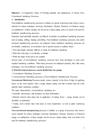
  • 2. 2 Material removal may occur with chip formation or even no chip formation may take place. For example in AJM, chips are of microscopic size and in case of Electrochemical machining material removal occurs due to electrochemical dissolution at atomic level. 2. NEED FOR UNCONVENTIONAL MACHINING PROCESSES i. Extremely hard and brittle materials or Difficult to machine material are difficult to machine by traditional machining processes. ii. When the workpiece is too flexible or slender to support the cutting or grinding forces. When the shape of the part is too complex. 4. CLASSIFICATION OF NON-CONVENTIONAL MACHINING PROCESSES: A. Mechanical Processes B. Electrochemical Processes i. Abrasive Jet Machining (AJM) i. Electrochemical Machining (ECM) ii. Ultrasonic Machining (USM) ii. Electro Chemical Grinding (ECG) iii. Water Jet Machining (WJM) iii. Electro Jet Drilling (EJD) iv. Abrasive Water Jet Machining (AWJM) C. Electro-Thermal Processes D. Chemical Processes i. Electro-discharge machining (EDM) i. Chemical Milling (CHM) ii. Laser Jet Machining (LJM) ii. Photochemical Milling (PCM) iii. Electron Beam Machining (EBM)  MECHANICAL PROCESSES 1. ABRASIVE JET MACHINING (AJM) In Abrasive Jet Machining (AJM), abrasive particles are made to impinge on the work material at a high velocity. The jet of abrasive particles is carried by carrier gas or air. The high velocity stream of abrasive is generated by converting the pressure energy of the carrier gas or air to its kinetic energy and hence high velocity jet. The nozzle directs the abrasive jet in a controlled manner onto the work material, so that the distance between the nozzle and the work piece and the impingement angle can be set desirably. The high velocity abrasive particles remove the material by micro-cutting action as well as brittle fracture of the work material. Fig. 1.1 schematically shows the material removal process.
  • 3. 3 Fig 1: AJM In AJM, generally, the abrasive particles of around 50 μm grit size would impinge on the work material at velocity of 200 m/s from a nozzle of I.D. of 0.5 mm with a standoff distance of around 2 mm. The kinetic energy of the abrasive particles would be sufficient to provide material removal due to brittle fracture of the work piece or even micro cutting by the abrasives. Working In AJM, air is compressed in an air compressor and compressed air at a pressure of around 5 bar is used as the carrier gas as shown in Fig. 1.2. Fig. 1.2 Also shows the other major parts of the AJM system. Gases like CO2, N2 can also be used as carrier gas which may directly be issued from a gas cylinder. Generally oxygen is not used as a carrier gas. Fig 2: AJM System The carrier gas is first passed through a pressure regulator to obtain the desired working pressure. The gas is then passed through an air dryer to remove any residual water vapour. To
  • 4. 4 remove any oil vapour or particulate contaminant the same is passed through a series of filters. Then the carrier gas enters a closed chamber known as the mixing chamber. The abrasive particles enter the chamber from a hopper through a metallic sieve. The sieve is constantly vibrated by an electromagnetic shaker. The mass flow rate of abrasive (15 gm/min) entering the chamber depends on the amplitude of vibration of the sieve and its frequency. The abrasive particles are then carried by the carrier gas to the machining chamber via an electro- magnetic on-off valve. The machining enclosure is essential to contain the abrasive and machined particles in a safe and eco-friendly manner. The machining is carried out as high velocity (200 m/s) abrasive particles are issued from the nozzle onto a work piece traversing under the jet.  Process Parameters and Machining Characteristics Abrasive: Material - Al2O3 / SiC / Glass beads Shape –Irregular / spherical Size – 10~50 μm Mass flow rate – 2 ~ 20 gm/min Carrier gas: Composition – Air, CO 2, N 2 Density – Air ~ 1.3 kg/m3 Velocity – 500 ~ 700 m/s Pressure – 2 ~ 10 bar Flow rate – 5 ~ 30 lpm Abrasive Jet: Velocity – 100 ~ 300 m/s Mixing ratio – mass flow ratio of abrasive to gas Stand-off distance – 0.5 ~ 5 mm Impingement Angle – 60 0 ~ 90 0 Nozzle: Material – WC Diameter – (Internal) 0.2 ~ 0.8 mm Life – 10 ~ 300 hours The important machining characteristics in AJM are: • The material removal rate (MRR) mm3/min or gm/min • The machining accuracy • The life of the nozzle  Applications • For drilling holes of intricate shapes in hard and brittle materials • For machining fragile, brittle and heat sensitive materials • AJM can be used for drilling, cutting, deburring, cleaning and etching. • Micro-machining of brittle materials  Limitations • MRR is rather low (around ~ 15 mm3/min for machining glass) • Abrasive particles tend to get embedded particularly if the work material is ductile • Tapering occurs due to flaring of the jet • Environmental load is rather high.
  • 5. 5 Fig 3: Effect of process parameters MRR 2. ABRASIVE WATER-JET MACHINING (AWJM) Abrasive water jet cutting is an extended version of water jet cutting; in which the water jet contains abrasive particles such as silicon carbide or aluminium oxide in order to increase the material removal rate above that of water jet machining. Almost any type of material ranging from hard brittle materials such as ceramics, metals and glass to extremely soft materials such as foam and rubbers can be cut by abrasive water jet cutting. The narrow cutting stream and computer controlled movement enables this process to produce parts accurately and efficiently. This machining process is especially ideal for cutting materials that cannot be cut by laser or thermal cut. Metallic, non-metallic and advanced composite materials of various thicknesses can be cut by this process. This process is particularly suitable for heat sensitive materials that cannot be machined by processes that produce heat while machining. The schematic of abrasive water jet cutting is shown in Figure 15 which is similar to water jet cutting apart from some more features underneath the jewel; namely abrasive, guard and mixing tube. In this process, high velocity water exiting the jewel creates a vacuum which sucks abrasive from the abrasive line, which mixes with the water in the mixing tube to form a high velocity beam of abrasives.
  • 6. 6 Applications Abrasive water jet cutting is highly used in aerospace, automotive and electronics industries. In aerospace industries, parts such as titanium bodies for military aircrafts, engine components (aluminium, titanium, heat resistant alloys), aluminium body parts and interior cabin parts are made using abrasive water jet cutting. In automotive industries, parts like interior trim (head liners, trunk liners, door panels) and fibre glass body components and bumpers are made by this process. Similarly, in electronics industries, circuit boards and cable stripping are made by abrasive water jet cutting. Fig 4: AWJ Machining Advantages of abrasive water jet cutting • In most of the cases, no secondary finishing required • No cutter induced distortion • Low cutting forces on workpieces • Limited tooling requirements • Little to no cutting burr • Typical finish 125-250 microns • Smaller kerf size reduces material wastages • No heat affected zone • Localises structural changes • No cutter induced metal contamination • Eliminates thermal distortion • No slag or cutting dross • Precise, multi plane cutting of contours, shapes, and bevels of any angle. Limitations of abrasive water jet cutting • Cannot drill flat bottom • Cannot cut materials that degrades quickly with moisture • Surface finish degrades at higher cut speeds which are frequently used for rough cut The major disadvantages of abrasive water jet cutting are high capital cost and high noise levels during operation.
  • 7. 7 3. Ultrasonic Machining (USM) USM is mechanical material removal process or an abrasive process used to erode holes or cavities on hard or brittle workpiece by using shaped tools, high frequency mechanical motion and an abrasive slurry. USM offers a solution to the expanding need for machining brittle materials such as single crystals, glasses and polycrystalline ceramics, and increasing complex operations to provide intricate shapes and workpiece profiles. It is therefore used extensively in machining hard and brittle materials that are difficult to machine by traditional manufacturing processes. The hard particles in slurry are accelerated toward the surface of the workpiece by a tool oscillating at a frequency up to 100 KHz - through repeated abrasions, the tool machines a cavity of a cross section identical to its own. A schematic representation of USM is shown in Figure. Fig 5: USM Machining Operation In ultrasonic machining, a tool of desired shape vibrates at an ultrasonic frequency (19 ~ 25 kHz) with an amplitude of around 15 – 50 μm over the workpiece. Generally the tool is pressed downward with a feed force, F. Between the tool and workpiece, the machining zone is flooded with hard abrasive particles generally in the form of a water based slurry. As the tool vibrates over the workpiece, the abrasive particles act as the indenters and indent both the work material and the tool. The abrasive particles, as they indent, the work material, would remove the same, particularly if the work material is brittle, due to crack initiation, propagation and brittle fracture of the material. Hence, USM is mainly used for machining brittle materials {which are poor conductors of electricity and thus cannot be processed by Electrochemical and Electro- discharge machining (ECM and ED)}. USM is primarily targeted for the machining of hard and brittle materials (dielectric or conductive) such as boron carbide, ceramics, titanium carbides, rubies, quartz etc. USM is a versatile machining process as far as properties of materials are concerned. This process is able to effectively machine all materials whether they are electrically conductive or insulator.
  • 8. 8 WORKING The basic mechanical structure of an USM is very similar to a drill press. However, it has additional features to carry out USM of brittle work material. The workpiece is mounted on a vice, which can be located at the desired position under the tool using a 2 axis table. The table can further be lowered or raised to accommodate work of different thickness. The typical elements of an USM are, 1. Slurry delivery and return system 2. Feed mechanism to provide a downward feed force on the tool during machining 3. The transducer, which generates the ultrasonic vibration 4. The horn or concentrator, which mechanically amplifies the vibration to the required amplitude of 15 – 50 μm and accommodates the tool at its tip. Fig 6: Schematic view of an Ultrasonic Machine The ultrasonic vibrations are produced by the transducer. The transducer is driven by suitable signal generator followed by power amplifier. The transducer for USM works on the following principle 1. Piezoelectric effect 3. Magnetostrictive effect 2. Electrostrictive effect Magnetostrictive transducers are most popular and robust amongst all. Fig. 7 shows a typical magnetostrictive transducer along with horn. The horn or concentrator is a wave-guide, which amplifies and concentrates the vibration to the tool from the transducer. Fig 7: Working of horn as Mechanical amplifier of amplitude of vibration
  • 9. 9 The horn or concentrator can be of different shape like Fig 8: Different Horns used in USM Process Parameters and their Effects. During discussion and analysis as presented in the previous section, the process parameters which govern the ultrasonic machining process have been identified and the same are listed below along with material parameters • Amplitude of vibration (ao) – 15 – 50 μm • Frequency of vibration (f) – 19 – 25 kHz • Feed force (F) – related to tool dimensions • Feed pressure (p) • Abrasive size – 15 μm – 150 μm • Abrasive material – Al2O3, SiC, B4C, Boronsilicarbide, Diamond • Flow strength of work material • Flow strength of the tool material • Contact area of the tool – A • Volume concentration of abrasive in water slurry – C • The machining tool must be selected to be highly wear resistant, such as high-carbon steels. The abrasives (25-60 µm in dia.) in the (water-based, up to 40% solid volume) slurry includes: Boron carbide, silicon carbide and aluminum oxide. Applications  Used for machining hard and brittle metallic alloys, semiconductors, glass, ceramics, carbides.  Used for machining round, square, irregular shaped holes and surface impressions.  Machining, wire drawing, punching or small blanking dies.
  • 10. 10 Fig 9: Effect of machining parameters on MRR Advantage of USM USM process is a non-thermal, non-chemical, creates no changes in the microstructures, chemical or physical properties of the workpiece and offers virtually stress free machined surfaces. • Any materials can be machined regardless of their electrical conductivity • Especially suitable for machining of brittle materials • Machined parts by USM possess better surface finish and higher structural integrity. • USM does not produce thermal, electrical and chemical abnormal surface Some disadvantages of USM • USM has higher power consumption and lower material-removal rates than traditional fabrication processes.
  • 11. 11 • Tool wears fast in USM. • Machining area and depth is restraint in USM.  ELECTRICAL ENERGY BASED PROCESSES 1. Electrical discharge machining (EDM) Electrical discharge machining is one of the most widely used non-traditional machining processes. The main attraction of EDM over traditional machining processes such as metal cutting using different tools and grinding is that this technique utilises thermoelectric process to erode undesired materials from the workpiece by a series of discrete electrical sparks between the workpiece and the electrode. A picture of EDM machine in operation. The traditional machining processes rely on harder tool or abrasive material to remove the softer material whereas non-traditional machining processes such as EDM uses electrical spark or thermal energy to erode unwanted material in order to create desired shape. So, the hardness of the material is no longer a dominating factor for EDM process. A schematic of an EDM process is shown in Figure 2, where the tool and the workpiece are immersed in a dielectric fluid. EDM removes material by discharging an electrical current, normally stored in a capacitor bank, across a small gap between the tool (cathode) and the workpiece (anode) typically in order. Fig 10: Working of EDM Working principle of EDM As shown in Figure 1, at the beginning of EDM operation, a high voltage is applied across the narrow gap between the electrode and the workpiece. This high voltage induces an electric field in the insulating dielectric that is present in narrow gap between electrode and workpiece.
  • 12. 12 This cause conducting particles suspended in the dielectric to concentrate at the points of strongest electrical field. When the potential difference between the electrode and the workpiece is sufficiently high, the dielectric breaks down and a transient spark discharges through the dielectric fluid, removing small amount of material from the workpiece surface. The volume of the material removed per spark discharge is typically in the range of 10-6 to 10- 6 mm3. The material removal rate, MRR, in EDM is calculated by the following foumula: MRR = 40 I / Tm 1.23 (cm3/min) Where, I is the current amp, Tm is the melting temperature of workpiece in 0C. Process Parameters The process parameters in EDM are mainly related to the waveform characteristics. Fig. 11 shows a general waveform used in EDM. Fig 11: Waveform used in EDM The waveform is characterised by the • The open circuit voltage - Vo • The working voltage - Vw • The maximum current - Io • The pulse on time – the duration for which the voltage pulse is applied - ton • The pulse off time – toff
  • 13. 13 • The gap between the workpiece and the tool – spark gap - δ • The polarity – straight polarity – tool (-ve) • The dielectric medium • External flushing through the spark gap Application of EDM The EDM process has the ability to machine hard, difficult-to-machine materials. Parts with complex, precise and irregular shapes for forging, press tools, extrusion dies, difficult internal shapes for aerospace and medical applications can be made by EDM process. Advantages of EDM The main advantages of DM are: • By this process, materials of any hardness can be machined; • No burrs are left in machined surface; • One of the main advantages of this process is that thin and fragile/brittle components can be machined without distortion; Limitations of EDM The main limitations of this process are: • This process can only be employed in electrically conductive materials; • Material removal rate is low and the process overall is slow compared to conventional machining processes; • Unwanted erosion and over cutting of material can occur; • Rough surface finish when at high rates of material removal. Dielectric fluids Dielectric fluids used in EDM process are hydrocarbon oils, kerosene and deionised water. The functions of the dielectric fluid are to: • Act as an insulator between the tool and the workpiece. • Act as coolant. • Act as a flushing medium for the removal of the chips. The electrodes for EDM process usually are made of graphite, brass, copper and copper- tungsten alloys. Design considerations for EDM process are as follows: • Deep slots and narrow openings should be avoided. • The surface smoothness value should not be specified too fine. • Rough cut should be done by other machining process. Only finishing operation should be done in this process as MRR for this process is low.
  • 14. 14  CHEMICAL AND ELECTRO CHEMICAL ENERGY BASED PROCESSES 1. Electrochemical Machining (ECM) Electrochemical machining (ECM) is a metal-removal process based on the principle of reverse electroplating. In this process, particles travel from the anodic material (workpiece) toward the cathodic material (machining tool). A current of electrolyte fluid carries away the deplated material before it has a chance to reach the machining tool. The cavity produced is the female mating image of the tool shape. Similar to EDM, the workpiece hardness is not a factor, making ECM suitable for machining difficult-to –machine materials. Difficult shapes can be made by this process on materials regardless of their hardness. A schematic representation of ECM process is shown in Figure 8. The ECM tool is positioned very close to the workpiece and a low voltage, high amperage DC current is passed between the workpiece and electrode. Some of the shapes made by ECM process is shown in Figure 9. Fig 12: Principle of Electro Chemical Machining (ECM) PROCESS During ECM, there will be reactions occurring at the electrodes i.e. at the anode or workpiece and at the cathode or the tool along with within the electrolyte. Let us take an example of machining of low carbon steel which is primarily a ferrous alloy mainly containing iron. For electrochemical machining of steel, generally a neutral salt solution of sodium chloride (NaCl) is taken as the electrolyte. The electrolyte and water undergoes ionic dissociation as shown below as potential difference is applied NaCl ↔ Na+ + Cl- H2O ↔ H + + (OH) As the potential difference is applied between the work piece (anode) and the tool (cathode), the positive ions move towards the tool and negative ions move towards the workpiece. Thus
  • 15. 15 the hydrogen ions will take away electrons from the cathode (tool) and from hydrogen gas as: 2H + + 2e- = H2↑ at cathode. Fig 13: Schematic representation of electro-chemical reactions Similarly, the iron atoms will come out of the anode (work piece) as: Fe = Fe+ + + 2e Within the electrolyte iron ions would combine with chloride ions to form iron chloride and similarly sodium ions would combine with hydroxyl ions to form sodium hydroxide Na + + OH- = NaOH In practice FeCl2 and Fe(OH)2 would form and get precipitated in the form of sludge. In this manner it can be noted that the work piece gets gradually machined and gets precipitated as the sludge. Moreover there is not coating on the tool, only hydrogen gas evolves at the tool or cathode. Fig. 2 depicts the electro-chemical reactions schematically. As the material removal takes place due to atomic level dissociation, the machined surface is of excellent surface finish and stress free. The voltage is required to be applied for the electrochemical reaction to proceed at a steady state. That voltage or potential difference is around 2 to 30 V. The applied potential difference, however, also overcomes the following resistances or potential drops. They are: • The electrode potential • The activation over potential • Ohmic potential drop • Concentration over potential • Ohmic resistance of electrolyte EQUIPMENT The electrochemical machining system has the following modules: • Power supply • Electrolyte filtration and delivery system • Tool feed system • Working tank Fig. 4 schematically shows an electrochemical drilling unit.
  • 16. 16 Fig 14: Schematic diagram of an electrochemical drilling unit Advantages of ECM • The components are not subject to either thermal or mechanical stress. • No tool wear during ECM process. • Fragile parts can be machined easily as there is no stress involved. • ECM deburring can debur difficult to access areas of parts. • High surface finish (up to 25 µm in) can be achieved by ECM process. • Complex geometrical shapes in high-strength materials particularly in the aerospace industry for the mass production of turbine blades, jet-engine parts and nozzles can be machined repeatedly and accurately. • Deep holes can be made by this process. Limitations of ECM • ECM is not suitable to produce sharp square corners or flat bottoms because of the tendency for the electrolyte to erode away sharp profiles. • ECM can be applied to most metals but, due to the high equipment costs, is usually used primarily for highly specialized applications. Material removal rate, MRR, in ECM MRR = C .I. h (cm3/min)
  • 17. 17 C: specific (material) removal rate (e.g., 0.2052 cm3/amp-min for nickel); I: current (amp); h: current efficiency (90–100%). The rates at which metal can electrochemically remove are in proportion to the current passed through the electrolyte and the elapsed time for that operation. Many factors other than current influence the rate of machining. These involve electrolyte type, rate of electrolyte flow, and some other process conditions. APPLICATION Fig 14: Different applications of Electro Chemical Machining  THERMAL ENERGY BASED PROCESSES 1. Laser–Beam Machining (LBM) Laser-beam machining is a thermal material-removal process that utilizes a high-energy, coherent light beam to melt and vaporize particles on the surface of metallic and non-metallic workpieces. Lasers can be used to cut, drill, weld and mark. LBM is particularly suitable for making accurately placed holes. A schematic of laser beam machining is shown in Figure.
  • 18. 18 Fig 15: LBM Different types of lasers are available for manufacturing operations which are as follows: • CO2 (pulsed or continuous wave): It is a gas laser that emits light in the infrared region. It can provide up to 25 kW in continuous-wave mode. • Nd:YAG: Neodymium-doped Yttrium-Aluminum-Garnet (Y3Al 5O12) laser is a solid- state laser which can deliver light through a fibre-optic cable. It can provide up to 50 kW power in pulsed mode and 1 kW in continuous-wave mode. Ruby-laser or crystalline aluminium oxide or saphire is the most commonly used solid state laser. Generally these lasers are fabricated in into rods having length about 150 mm. Their ends are well furnished to close optical tolerances. Figure below shows a schematic view of laser beam machining process. A small amount of chromium oxide is added to dope the ruby crystal. A flash of high intensity light , generally Xenon-filled flash lamp is used to pump the laser. To fire the xenon lamp a large capacitor is required to be discharged through it and 250 to 1000 watts of electric power is needed to do this. The intense radiation discharged from the lamp excites the fluorescent impurity atoms (chromium atoms) and these atoms reaches a higher energy level. After passing through a series of energy levels when the atoms fall back to original energy level , an intense beam of visible light emission is observed. This beam is reflected back from the coated rod ends and make more and more atoms excited and stimulated and return to ground level. A stimulated avalanche of light is obtained which is transmitted through the coated part (~80% reflective). This light which is highly coherent in time and space has a very narrow frequency band, is highly in phase and quite parallel. If this light is focused in association with ordinary lenses on the desired spot of the w/p, high energy density is gained which helps to melt and vaporize the metal.
  • 19. 19 Applications LBM can make very accurate holes as small as 0.005 mm in refractory metals ceramics, and composite material without warping the workpieces. This process is used widely for drilling. Laser beam cutting (drilling) • In drilling, energy transferred (e.g., via a Nd:YAG laser) into the workpiece melts the material at the point of contact, which subsequently changes into a plasma and leaves the region. • A gas jet (typically, oxygen) can further facilitate this phase transformation and departure of material removed. • Laser drilling should be targeted for hard materials and hole geometries that are difficult to achieve with other methods. A typical SEM micrograph hole drilled by laser beam machining process employed in making a hole is shown in Figure 13. Laser beam cutting (milling) • A laser spot reflected onto the surface of a workpiece travels along a prescribed trajectory and cuts into the material. • Continuous-wave mode (CO 2) gas lasers are very suitable for laser cutting providing high- average power, yielding high material-removal rates, and smooth cutting surfaces. Advantage of laser cutting • No limit to cutting path as the laser point can move any path. • The process is stress less allowing very fragile materials to be laser cut without any support. • Very hard and abrasive material can be cut. • Sticky materials are also can be cut by this process. • It is a cost effective and flexible process. • High accuracy parts can be machined. • No cutting lubricants required • No tool wear • Narrow heat effected zone Limitations of laser cutting • Uneconomic on high volumes compared to stamping • Limitations on thickness due to taper • High capital cost • High maintenance cost • Assist or cover gas required
  • 20. 20 10. ELECTRON BEAM MACHINING (EBM) Electron Beam Machining (EBM) and Laser Beam Machining (LBM) are thermal processes considering the mechanisms of material removal. However electrical energy is used to generate high-energy electrons in case of Electron Beam Machining (EBM) and high-energy coherent photons in case of Laser Beam Machining (LBM). Thus these two processes are often classified as electro-optical-thermal processes. There are different jet or beam processes, namely Abrasive Jet, Water Jet etc. These two are mechanical jet processes. There are also thermal jet or beams. A few are oxyacetylene flame, welding arc, plasma flame etc. EBM as well as LBM are such thermal beam processes. Fig. 9.6.1 shows the variation in power density vs. the characteristic dimensions of different thermal beam processes. Characteristic length is the diameter over which the beam or flame is active. In case of oxyacetylene flame or welding arc, the characteristic length is in mm to tens of mm and the power density is typically low. Electron Beam may have a characteristic length of tens of microns to mm depending on degree of focusing of the beam. In case of defocused electron beam, power density would be as low as 1 Watt/mm2. But in case of focused beam the same can be increased to tens of kW/mm2. Similarly as can be seen in Fig. 16, laser beams can be focused over a spot size of 10 – 100 μm with a power density as high as 1 MW/mm2. Electrical discharge typically provides even higher power density with smaller spot size. Fig 16: Variation in energy density with spot diameter of thermal beam processes Process Electron beam is generated in an electron beam gun. The construction and working principle of the electron beam gun would be discussed in the next section. Electron beam gun provides high velocity electrons over a very small spot size. Electron Beam Machining is required to be
  • 21. 21 carried out in vacuum. Otherwise the electrons would interact with the air molecules, thus they would loose their energy and cutting ability. Thus the workpiece to be machined is located under the electron beam and is kept under vacuum. The high-energy focused electron beam is made to impinge on the workpiece with a spot size of 10 – 100 μm. The kinetic energy of the high velocity electrons is converted to heat energy as the electrons strike the work material. Due to high power density instant melting and vaporisation starts and “melt – vaporisation” front gradually progresses, as shown in Fig. 17. Finally the molten material, if any at the top of the front, is expelled from the cutting zone by the high vapour pressure at the lower part. Unlike in Electron Beam Welding, the gun in EBM is used in pulsed mode. Holes can be drilled in thin sheets using a single pulse. For thicker plates, multiple pulses would be required. Electron beam can also be manoeuvred using the electromagnetic deflection coils for drilling holes of any shape. Equipment Fig. 17, shows the schematic representation of an electron beam gun, which is the heart of any electron beam machining facility. The basic functions of any electron beam gun are to generate free electrons at the cathode, accelerate them to a sufficiently high velocity and to focus them over a small spot size. Further, the beam needs to be manoeuvred if required by the gun. The cathode as can be seen in Fig. 9.6.3 is generally made of tungsten or tantalum. Such cathode filaments are heated, often inductively, to a temperature of around 25000C. Such heating leads to thermo-ionic emission of electrons, which is further enhanced by maintaining very low vacuum within the chamber of the electron beam gun. Moreover, this cathode cartridge is highly negatively biased so that the thermo-ionic electrons are strongly repelled away form the cathode. This cathode is often in the form of a cartridge so that it can be changed very quickly to reduce down time in case of failure. Fig 17: Mechanismof Material Removal
  • 22. 22 Parameters The process parameters, which directly affect the machining characteristics in Electron Beam Machining, are: • The accelerating voltage • The beam current • Pulse duration • Energy per pulse • Power per pulse • Lens current • Spot size • Power density ADVANTAGES OF EBM: Large depth-to-width ratio of material penetrated by the beam with applications of very fine hole drilling becoming feasible There is a minimum number of pulses ne associated with an optimum accelerating voltage. In practice the number of pulses to produce a given hole depth is usually found to decrease with increase in accelerating voltage.  CHEMICAL PROCESSES 1. Chemical Machining Chemical machining (CHM) process is a controlled chemical dissolution (CD) of a workpiece material by contact with strong reagent (etchant). Special coatings called maskants protect areas from which the metal is not to be machined. It is one of the non-conventional machining processes. The advancement of technology causes to the development of many hard-to- machine materials: stainless steel, super alloys, ceramics, refractories and fiber-reinforced composites due to their high hardness, strength, brittleness, toughness and low machinability properties. Sometimes, the machined components require high surface finish and dimensional accuracy, complicated shape and special size, which cannot be achieved by the conventional machining processes. Moreover, the rise in temperature and the residual stresses generated in the workpiece due to traditional machining processes may not be acceptable. These requirements have led to the development of non- traditional machining (NTM) processes. In these processes, the conventional cutting tools which are not employed. Instead, energy in its direct form is utilized. Chemical energy is used in chemical machining. This process is the precision contouring of metal into any size, shape or form without the use of physical force, by a controlled chemical reaction. Material is removed by microscopic electrochemical cell action, as occurs in corrosion or chemical dissolution of a metal.
  • 23. 23 This controlled chemical dissolution will simultaneously etch all exposed surfaces even though the penetration rates of the etch may be only 0.0005–0.0030 in./min. The basic process takes many forms: chemical milling of pockets, contours, overall metal removal, chemical blanking for etching through thin sheets; photochemical machining (PCM) for etching by using of photosensitive resists in microelectronics; chemical or electrochemical polishing where weak chemical reagents are used (sometimes with remote electric assist) for polishing or deburring and chemical jet machining where a single chemically active jet is used. Chemical machining offers virtually unlimited scope for engineering and design ingenuity, to gain the most from its unique characteristics, chemical machining should be approached with the idea that this industrial tool can do jobs not practical or possible with any other metal working methods. Chemical machining will likely prove to be of considerable value in the solution of problems that are constantly arising as the result of the introduction of new materials. In comparison with other machining processes, chemical machining has many advantages, but with some limitations. The most important advantages are: weight reduction is possible on complex contours that are difficult to machine using conventional methods; decorative finishes and extensive thin-web areas are possible to be machined; CHM does have low scrap rates (3 percent); no burrs are formed; no stress is introduced to the workpiece, which minimizes the part distortion and makes machining of delicate parts possible; a continuous taper on contoured sections is achievable; the capital cost of equipment, used for machining large components, is relatively low; small thickness of metal can be removed; the good surface quality in addition to the absence of burrs eliminate the need for finishing operations. The limitations of CHM are: Handling and disposal of chemicals can be troublesome; hand masking, scribing, and stripping can be time consuming, repetitive, and tedious and design changes can be implemented quickly; metallurgical homogeneous surfaces are required for best results; slower process, very low MRR so high cost of operation; deep narrow cuts are difficult to produce; difficult to get sharp corner; hydrogen pickup and intergranular attack are a problem with some materials; complex designs become expensive; simultaneous material removal, from all surfaces, improves productivity and reduces wrapping; the straightness of the walls is subjected to fillet and undercutting limitations; difficult to chemically machine thick material (limit is depended on workpiece material, but the thickness should be around maximum (10mm); porous materials and part designs that have deep, narrow cavities or folded-metal seams should be avoided.
  • 24. 24 Applications of CHM Nontraditional machining processes are widely used to manufacture geometrically complex and precision parts for aerospace, electronics and automotive and many other industries. There are different geometrically designed parts, such as deep internal cavities, miniaturized microelectronics and nontraditional machining processes may only produce fine quality components. All the common metals including aluminum, copper, zinc, steel, lead, and nickel can be chemically machined. Many exotic metals such as titanium, molybdenum, and zirconium, as well as nonmetallic materials including glass, ceramics, and some plastics, can also be used with the process. CHM applications range from large aluminum alloy airplane wing parts to minute integrated circuit chips. The practical depth of cut ranges between 2.54 to 12.27 mm. Shallow cuts in large thin sheets are of the most popular application especially for weight reduction of aerospace components. Multiple designs can be machined from the same sheet at the same time. CHM is used to thin out walls, webs, and ribs of parts that have been produced by forging, casting, or sheet metal forming. Conclusion: In the latest field of technology respect to welding and machining, plasma arc welding and machining have a huge success. Due to its improved weld quality and increased weld output it is been used for precision welding of surgical instruments, to automatic repair of jet engine blades to the manual welding for repair of components in the tool, die and mold industry. But due to its high equipment expense and high production of ozone, it’s been outnumbered by other advance welding equipment like laser beam welding and electro beam welding.