Long journey of Ruby Standard library at RubyKaigi 2024
Lecture2 networkclassification
1. Lecture 2
Transmission Rate: The amount of data transferred per unit time from source to
destination is called as transmission rate. Remember one thing, that the transmission rate
is the property of machine (the rate at which machine is sending). Units are bits/sec.
Propagation Delay: The amount of time taken per unit time, for the data to reach the
destination and acknowledgment to come back to the source is called as propagation
delay. Units are sec.
Data Rate or Channel Capacity or Link Capacity: The amount of data per unit time
which the medium is sending or transmitting through itself is called as Data Rate. Units
are bits/sec. Remember that Data Rate or channel capacity is the property of medium and
not of the machine. We will discuss later about the mathematical formulae given by
Nyquist to calculate the data rate or channel capacity of a noiseless medium and another
formulae by Shannon, called as Shannon channel capacity, which calculates the data rate
for a noisy medium.
Topology: Topology is defined as how the nodes in a network are physically placed.
Key Elements of a LAN
The key elements of a LAN are
1. Topology
2. Transmission Medium
3. Medium Access Control
Together these elements decide the cost and capacity of the LAN, but also the type of
data that can be transmitted, the speed and efficiency of applications.
In terms of communication network, topology is defined as the way nodes or systems in a
network are physically laid out. The common topologies for LAN are bus, tree, ring, star
and mesh.
Classification of Distance on the basis of Physical Layout or topology
There are five possible classifications on the basis of topology or physical layout.
1. Bus
2. Star
3. Ring
4. Mesh
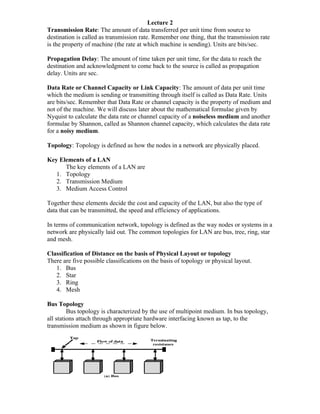
Bus Topology
Bus topology is characterized by the use of multipoint medium. In bus topology,
all stations attach through appropriate hardware interfacing known as tap, to the
transmission medium as shown in figure below.
2. A transmission from any station propagates the length of the medium in both the
directions and can be received by all other stations in the network. At each end of the bus
is a terminator, which absorbs any signal, and thus removing it from the bus.
In bus topology, any transmission made, will propagate through the medium and will be
received by all stations in the network, so we require some way of indicating for whom
the transmission is intended, i.e. who is the intended recipient. To solve this problem,
station transmits in small blocks, called as frames, and each frame contains the date and
frame header. Each station has a physical address, and this physical address is included in
the frame header. The transmission happens as shown below.
There is another problem associated with the bus topology, and it is controlling the access
of the medium i.e. Medium Access Control. If two stations wish to transmit at the same
moment of time, then their frames will collide and hence garbled up. So some mechanism
is needed for controlling the access of medium among the stations. This we will discuss
later in MAC.
3. Tree Topology
Actually bus is a special case of tree, with only one trunk and no branches. The
transmission medium is a branching cable with no closed loops as shown in the figure
below. The tree layout begins at a point known as headend. One or more cables start at
the headend, and each of these may have branches. As with the bus, transmission from
any station will propagate throughout the medium, received by all the stations and finally
at each end there are terminators, which absorb the signals.
In bus topology, any transmission made, will propagate through the medium and will be
received by all stations in the network, so we require some way of indicating for whom
the transmission is intended, i.e. who is the intended recipient. To solve this problem,
station transmits in small blocks, called as frames, and each frame contains the date and
frame header. Each station has a physical address, and this physical address is included in
the frame header.
Transmission Media for Bus LANs
There are four possible alternatives that can be used for Bus LANs
1. Twisted Pair:
2. Baseband Coaxial Cable
3. Broadband Coaxial Cable
4. Optical Fiber
Ring Topology
In ring topology, the network consists of stations joined together in a ring like
fashion through point-to-point links. These links are unidirectional i.e. data circulate
around the ring in one direction. In ring topology token passing technique is used. a
special control frame called as token. Generally this token propagates around the logical
ring, with only the token holder being permitted to transmit frame. Since only one station
can hold the token at a time, and there is only one token in the ring, no collisions can
occur. This access method is called as token passing. After a station get hold of the
token, he starts transmitting the data. A token with the data is known as frame, so a frame
is placed on the transmission medium, which also contains the address of intended
recipient. All the station in the network can receive the packet, but only intended receipt
will copy the contents of the frame, and finally when the frame reaches again to the
source, he removes the data from the frame.
4. The above diagram shows, how frame transmission happens in the case of ring LAN.
Star Topology
In the star LAN topology, each station is directly connected to a common central
node. Each station attaches to a central node via two point-to-point links, one for
transmission and one for reception. The central node act as frame switching device. An
incoming frame is buffered in the central node and then retransmitted on an outgoing link
to the destination station.
5. Mesh Topology
There is another topology, in which each computer is directly connected to every other
computer in the network; such a topology is called as mesh topology.
The only disadvantage with Mesh topology is that lots of wires are required whereas
there are lots of advantages.
1. No central dependency.
2. Data can be transmitted directly from one computer to another computer or
indirectly if any link is broken. So this means Mesh topology is reliable and
robust also compared to other topologies.
For more discussion on LAN topology refer to Brendan Tangney.
You should be able to answer the following question.
What is the difference between various topologies, and also you should be able to write
short notes on each topology, covering every point.
Classification of Network on the basis of Distance
There are three classification of LAN on the basis of distance
1. LAN
2. MAN
3. WAN
LAN: LAN is an acronym for Local Area Network. A LAN is a kind of network, where
the network spans within a range of certain Km, in other words network is local. For
Example: Computers communicated to each other in a lab forms a LAN. Infact multiple
departmental labs in a campus or university connected to each other form a network of
LANs i.e. A campus, where computers in mechanical lab are connected with each other,
that may in turn be connected to computers civil engineering through a networking
device like bridge or switch or hub.
1. So LAN means, connecting computers in local area.
2. In LAN networking devices like hubs, repeaters or bridges are used.
3. LAN topology generally consists of Bus and Ring.
4. LAN forms a multipoint network.
5. LAN topology has a major overhead of medium allocation, as LAN form a
multipoint network which means, multiple devise share the network so who
should gain access to the network (It’s obvious that all of them cannot access the
network simultaneously). We will discuss this problem in detail later, and this
problem is known as Medium Allocation Problem.
Example of LAN
MAN: MAN is an acronym for Metropolitan Area Network. A MAN is a network, where
the network spans across the cities i.e. interconnecting cities. For example, an
organization has an office in Muscat and another office in salalah, so connecting the
computers of office in Muscat with the office in salalah forms a MAN.
6. 1. So MAN means, connecting computers or network across cities.
2. Routers are used for interconnecting networks present in two different cities.
3. We are concerned about routing efficient strategies.
WAN: WAN is an acronym for Wide Area Network. A WAN is a network, where the
network spans across continents i.e. connecting countries. For example an organization
has one office in Oman, office in INDIA and another office in USA, so connecting the
computer of all the three offices together through a network is called as WAN.
1. In WAN networking devices like routers and satellites are used.
2. So WAN means, connecting computers or network across continents.
3. WAN topology may consist of star, tree, mesh, satellite.
Example of WAN
Subnet is the above diagram can be defined as a network which consist of routers, a
network that consist of network devices and helps in connecting two distant networks is
called as subnet.