SlideShare une entreprise Scribd logo
1  sur  13
TRACES OF THE LINE:-
THESE ARE THE POINTS OF INTERSECTIONS OF A LINE ( OR IT’S EXTENSION )
WITH RESPECTIVE REFFERENCE PLANES.
A LINE ITSELF OR IT’S EXTENSION, WHERE EVER TOUCHES H.P.,
THAT POINT IS CALLED TRACE OF THE LINE ON H.P.( IT IS CALLED H.T.)
SIMILARLY, A LINE ITSELF OR IT’S EXTENSION, WHERE EVER TOUCHES V.P.,
THAT POINT IS CALLED TRACE OF THE LINE ON V.P.( IT IS CALLED V.T.)
V.T.:- It is a point on Vp.
Hence it is called Fv of a point in Vp.
Hence it’s Tv comes on XY line.( Here onward named as v )
H.T.:- It is a point on Hp.
Hence it is called Tv of a point in Hp.
Hence it’s Fv comes on XY line.( Here onward named as ’h’ )
GROUP (B)
PROBLEMS INVOLVING TRACES OF THE LINE.
1. Begin with FV. Extend FV up to XY line.
2. Name this point h’
( as it is a Fv of a point in Hp)
3. Draw one projector from h’.
4. Now extend Tv to meet this projector.
This point is HT
STEPS TO LOCATE HT.
(WHEN PROJECTIONS ARE GIVEN.)
1. Begin with TV. Extend TV up to XY line.
2. Name this point v
( as it is a Tv of a point in Vp)
3. Draw one projector from v.
4. Now extend Fv to meet this projector.
This point is VT
STEPS TO LOCATE VT.
(WHEN PROJECTIONS ARE GIVEN.)
h’
HTVT’
v
a’
x y
a
b’
FV
b
TV
Observe & note :-
1. Points h’ & v always on x-y line.
2. VT’ & v always on one projector.
3. HT & h’ always on one projector.
4. FV - h’- VT’ always co-linear.
5. TV - v - HT always co-linear.
These points are used to
solve next three problems.
x y
b’ b’1
a
v
VT’
a’
HT
b
h’
b1
∅
300
θ
450
PROBLEM 6 :- Fv of line AB makes 450
angle with XY line and measures 60 mm.
Line’s Tv makes 300
with XY line. End A is 15 mm above Hp and it’s VT is 10 mm
below Hp. Draw projections of line AB,determine inclinations with Hp & Vp and locate HT, VT.
15
10
SOLUTION STEPS:-
Draw xy line, one projector and
locate fv a’ 15 mm above xy.
Take 450
angle from a’ and
marking 60 mm on it locate point b’.
Draw locus of VT, 10 mm below xy
& extending Fv to this locus locate VT.
as fv-h’-vt’ lie on one st.line.
Draw projector from vt, locate v on xy.
From v take 300
angle downward as
Tv and it’s inclination can begin with v.
Draw projector from b’ and locate b I.e.Tv point.
Now rotating views as usual TL and
it’s inclinations can be found.
Name extension of Fv, touching xy as h’
and below it, on extension of Tv, locate HT.
a’
b’
FV
30
45
10
LOCUS OF b’ & b’1
X Y
450
VT’
v
HT
h’
LOCUS OF b & b1
100
a
b
TV
b’1
θ
TL
Φ
TL
b1
PROBLEM 7 :
One end of line AB is 10mm above Hp and other end is 100 mm in-front of Vp.
It’s Fv is 450
inclined to xy while it’s HT & VT are 45mm and 30 mm below xy respectively.
Draw projections and find TL with it’s inclinations with Hp & VP.
SOLUTION STEPS:-
Draw xy line, one projector and
locate a’ 10 mm above xy.
Draw locus 100 mm below xy for points b & b1
Draw loci for VT and HT, 30 mm & 45 mm
below xy respectively.
Take 450
angle from a’ and extend that line backward
to locate h’ and VT, & Locate v on xy above VT.
Locate HT below h’ as shown.
Then join v – HT – and extend to get top view end b.
Draw projector upward and locate b’ Make a b & a’b’ dark.
Now as usual rotating views find TL and it’s inclinations.
X y
HT
VT
h’
a’
v
b’
a
b
80
50
b’1
θ
Φ
TL
TL
FV
TV
b 1
10
35
55
Locus of a’
PROBLEM 8 :- Projectors drawn from HT and VT of a line AB
are 80 mm apart and those drawn from it’s ends are 50 mm apart.
End A is 10 mm above Hp, VT is 35 mm below Hp
while it’s HT is 45 mm in front of Vp. Draw projections,
locate traces and find TL of line & inclinations with Hp and Vp.
SOLUTION STEPS:-
1.Draw xy line and two projectors,
80 mm apart and locate HT & VT ,
35 mm below xy and 55 mm above xy
respectively on these projectors.
2.Locate h’ and v on xy as usual.
3.Now just like previous two problems,
Extending certain lines complete Fv & Tv
And as usual find TL and it’s inclinations.
b1
a’
FV
VT’
v
TV
X Y
b’
a
b
θ
Φ
b1’
TL
TL
Then from point v & HT
angles can be drawn.
&
From point VT’ & h’
angles can be drawn.θα &
Φβ &
Instead of considering a & a’ as projections of first point,
if v & VT’ are considered as first point , then true inclinations of line with
Hp & Vp i.e. angles θ & Φ can be constructed with points VT’ & V respectively.
THIS CONCEPT IS USED TO SOLVE
NEXT THREE PROBLEMS.
PROBLEM 9 :-
Line AB 100 mm long is 300
and 450
inclined to Hp & Vp respectively.
End A is 10 mm above Hp and it’s VT is 20 mm below Hp
.Draw projections of the line and it’s HT.
X Y
VT’
v
10
20
Locus of a & a1’
θ (300
)
Φ(450
)
a1’
100 mm
b1’
b1
a1
100 mm
b’
a’
b
a
FV
TV
HT
h’
SOLUTION STEPS:-
Draw xy, one projector
and locate on it VT and V.
Draw locus of a’ 10 mm above xy.
Take 300
from VT and draw a line.
Where it intersects with locus of a’
name it a1’ as it is TL of that part.
From a1’ cut 100 mm (TL) on it and locate point b1’
Now from v take 450
and draw a line downwards
& Mark on it distance VT-a1’ I.e.TL of extension & name it a1
Extend this line by 100 mm and mark point b1.
Draw it’s component on locus of VT’
& further rotate to get other end of Fv i.e.b’
Join it with VT’ and mark intersection point
(with locus of a1’ ) and name it a’
Now as usual locate points a and b and h’ and HT.
PROBLEM 10 :-
A line AB is 75 mm long. It’s Fv & Tv make 450
and 600
inclinations with X-Y line resp
End A is 15 mm above Hp and VT is 20 mm below Xy line. Line is in first quadrant.
Draw projections, find inclinations with Hp & Vp. Also locate HT.
X Y
VT’
v
15
20
Locus of a & a1’ a1’
75 mm
b1’
b1
a1
75 mm
b’
a’
b
a
FV
TV
HT
h’
450
600
θ
Φ
SOLUTION STEPS:-
Similar to the previous only change
is instead of line’s inclinations,
views inclinations are given.
So first take those angles from VT & v
Properly, construct Fv & Tv of extension,
then determine it’s TL( V-a1)
and on it’s extension mark TL of line
and proceed and complete it.
PROBLEM 11 :- The projectors drawn from VT & end A of line AB are 40mm apart.
End A is 15mm above Hp and 25 mm in front of Vp. VT of line is 20 mm below Hp.
If line is 75mm long, draw it’s projections, find inclinations with HP & Vp
X Y
40mm
15
20
25
v
VT’
a’
a
a1’
b1’b’
b
TV
FV
75m
m
b1
θ
Φ
Draw two projectors for VT & end A
Locate these points and then
YES !
YOU CAN COMPLETE IT.
X
A.I.P.
GROUP (C)
CASES OF THE LINES IN A.V.P., A.I.P. & PROFILE PLANE.
α
αa’
b’ Line AB is in AIP as shown in above figure no 1.
It’s FV (a’b’) is shown projected on Vp.(Looking in arrow direction)
Here one can clearly see that the
Inclination of AIP with HP = Inclination of FV with XY line
Line AB is in AVP as shown in above figure no 2..
It’s TV (a b) is shown projected on Hp.(Looking in arrow direction)
Here one can clearly see that the
Inclination of AVP with VP = Inclination of TV with XY line
A.V.P.
β
A
B
β
a b
B
A
PPVP
HP
a
b
a’
b’
a”
b”
X Y
FV
TV
LSV
A
B
a
b
a’
b’
For F.V.
For T.V.
LINE IN A PROFILE PLANE ( MEANS IN A PLANE PERPENDICULAR TO BOTH HP & VP)
Results:-
1. TV & FV both are vertical, hence arrive on one single projector.
2. It’s Side View shows True Length ( TL)
3. Sum of it’s inclinations with HP & VP equals to 900
(
4. It’s HT & VT arrive on same projector and can be easily located
From Side View.
θ Φ+ = 900
)
ORTHOGRAPHIC PATTERN OF LINE IN PROFILE PLANE
HT
VT
θ
Φ
PROBLEM 12 :- Line AB 80 mm long, makes 300
angle with Hp
and lies in an Aux.Vertical Plane 450
inclined to Vp.
End A is 15 mm above Hp and VT is 10 mm below X-y line.
Draw projections, fine angle with Vp and Ht.
VT
v
X Y
a
b
a’
b’
a1’
b1
’
Locus of b’
Locus of b’
10
15
HT
h’
θ
b1
Φ
AVP 450
to VP
450
Locus of a’ & a1’
Simply consider inclination of AVP
as inclination of TV of our line,
well then?
You sure can complete it
as previous problems!
Go ahead!!
PROBLEM 13 :- A line AB, 75mm long, has one end A in Vp. Other end B is 15 mm above Hp
and 50 mm in front of Vp.Draw the projections of the line when sum of it’s
Inclinations with HP & Vp is 900
, means it is lying in a profile plane.
Find true angles with ref.planes and it’s traces.
a
b
HT
VT
X Y
a’
b’
Side View
( True Length )
a”
b”
(HT)
(VT)
HP
VP
Front view
top view
SOLUTION STEPS:-
After drawing xy line and one projector
Locate top view of A I.e point a on xy as
It is in Vp,
Locate Fv of B i.e.b’15 mm above xy as
it is above Hp.and Tv of B i.e. b, 50 mm
below xy asit is 50 mm in front of Vp
Draw side view structure of Vp and Hp
and locate S.V. of point B i.e. b’’
From this point cut 75 mm distance on Vp and
Mark a’’ as A is in Vp. (This is also VT of line.)
From this point draw locus to left & get a’
Extend SV up to Hp. It will be HT. As it is a Tv
Rotate it and bring it on projector of b.
Now as discussed earlier SV gives TL of line
and at the same time on extension up to Hp & Vp
gives inclinations with those panes.
θ
Φ

Contenu connexe

Tendances

Engineering drawing-part-3
Engineering drawing-part-3Engineering drawing-part-3
Engineering drawing-part-3
musadoto
 
Projection of solids
Projection of solidsProjection of solids
Projection of solids
Sumit Chandak
 
Projection of planes 038
Projection of planes 038Projection of planes 038
Projection of planes 038
Akash Sood
 
Projection of lines with problems
Projection of lines with problemsProjection of lines with problems
Projection of lines with problems
India
 

Tendances (20)

Eg projection of plane
Eg projection of planeEg projection of plane
Eg projection of plane
 
Engineering drawing-part-3
Engineering drawing-part-3Engineering drawing-part-3
Engineering drawing-part-3
 
Section of solids - ENGINEERING DRAWING/GRAPHICS
Section of solids - ENGINEERING DRAWING/GRAPHICSSection of solids - ENGINEERING DRAWING/GRAPHICS
Section of solids - ENGINEERING DRAWING/GRAPHICS
 
Projection of Lines
Projection of LinesProjection of Lines
Projection of Lines
 
Projection of solids
Projection of solidsProjection of solids
Projection of solids
 
Projections of Planes
Projections of PlanesProjections of Planes
Projections of Planes
 
Projection of planes 038
Projection of planes 038Projection of planes 038
Projection of planes 038
 
Projection of lines(new)
Projection of lines(new)Projection of lines(new)
Projection of lines(new)
 
Projection of lines(new)
Projection of lines(new)Projection of lines(new)
Projection of lines(new)
 
Development of surfaces of solids
Development of surfaces of solidsDevelopment of surfaces of solids
Development of surfaces of solids
 
Sections of Solids
Sections of SolidsSections of Solids
Sections of Solids
 
Projection of Planes- Engineering Graphics
Projection of Planes- Engineering GraphicsProjection of Planes- Engineering Graphics
Projection of Planes- Engineering Graphics
 
Section of solids
Section of solidsSection of solids
Section of solids
 
Projection of Lines
Projection of LinesProjection of Lines
Projection of Lines
 
Projection of solids
Projection of solidsProjection of solids
Projection of solids
 
Lesson 2 Projections of Straight Lines - Part II
Lesson 2 Projections of Straight Lines - Part IILesson 2 Projections of Straight Lines - Part II
Lesson 2 Projections of Straight Lines - Part II
 
Unit iii projection of solids converted
Unit  iii projection of solids convertedUnit  iii projection of solids converted
Unit iii projection of solids converted
 
Projection of lines
Projection of linesProjection of lines
Projection of lines
 
Projection of lines with problems
Projection of lines with problemsProjection of lines with problems
Projection of lines with problems
 
Unit ii projection of planes
Unit  ii projection of planesUnit  ii projection of planes
Unit ii projection of planes
 

Similaire à Engineering drawing-part-4

Engineering-Drawing-Part-4[1].ppt
Engineering-Drawing-Part-4[1].pptEngineering-Drawing-Part-4[1].ppt
Engineering-Drawing-Part-4[1].ppt
CHANDUS31
 
Engineering graphics lines
Engineering graphics linesEngineering graphics lines
Engineering graphics lines
student
 
PROJECTION OF LINES(new).ppt
PROJECTION OF LINES(new).pptPROJECTION OF LINES(new).ppt
PROJECTION OF LINES(new).ppt
dattu33
 
Projection-of-Point-and-lines-engineering108.com (1).ppt
Projection-of-Point-and-lines-engineering108.com (1).pptProjection-of-Point-and-lines-engineering108.com (1).ppt
Projection-of-Point-and-lines-engineering108.com (1).ppt
JanakiRaman206018
 
Projection-of-Point-and-lines-engineering108.com.ppt
Projection-of-Point-and-lines-engineering108.com.pptProjection-of-Point-and-lines-engineering108.com.ppt
Projection-of-Point-and-lines-engineering108.com.ppt
Mayur956299
 
Projection of straight lines I.pdf
Projection of straight lines I.pdfProjection of straight lines I.pdf
Projection of straight lines I.pdf
MuditKumar59
 

Similaire à Engineering drawing-part-4 (20)

Engineering-Drawing-Part-4[1].ppt
Engineering-Drawing-Part-4[1].pptEngineering-Drawing-Part-4[1].ppt
Engineering-Drawing-Part-4[1].ppt
 
projection of planes
projection of planesprojection of planes
projection of planes
 
Projection of-point-and-lines-engineering
Projection of-point-and-lines-engineeringProjection of-point-and-lines-engineering
Projection of-point-and-lines-engineering
 
Projections of lines modified.ppt
Projections of lines modified.pptProjections of lines modified.ppt
Projections of lines modified.ppt
 
Projection of lines
Projection of linesProjection of lines
Projection of lines
 
TRACES OF LINES IN SPACE USING ORTHOGRAPHIC PROJECTION
TRACES OF LINES IN SPACE USING ORTHOGRAPHIC PROJECTIONTRACES OF LINES IN SPACE USING ORTHOGRAPHIC PROJECTION
TRACES OF LINES IN SPACE USING ORTHOGRAPHIC PROJECTION
 
TRACES OF LINES IN SPACE USING ORTHOGRAPHIC PROJECTION
TRACES OF LINES IN SPACE USING ORTHOGRAPHIC PROJECTIONTRACES OF LINES IN SPACE USING ORTHOGRAPHIC PROJECTION
TRACES OF LINES IN SPACE USING ORTHOGRAPHIC PROJECTION
 
PROJECTION OF LINES.ppt
PROJECTION OF LINES.pptPROJECTION OF LINES.ppt
PROJECTION OF LINES.ppt
 
Eg 2
Eg 2Eg 2
Eg 2
 
2.1 PROJECTION OF LINES.ppt
2.1 PROJECTION OF LINES.ppt2.1 PROJECTION OF LINES.ppt
2.1 PROJECTION OF LINES.ppt
 
Engineering graphics lines
Engineering graphics linesEngineering graphics lines
Engineering graphics lines
 
Engerring Drawing by Deepak
Engerring Drawing by DeepakEngerring Drawing by Deepak
Engerring Drawing by Deepak
 
PROJECTION OF LINES(new).ppt
PROJECTION OF LINES(new).pptPROJECTION OF LINES(new).ppt
PROJECTION OF LINES(new).ppt
 
Engineering Graphics-Lines
Engineering Graphics-LinesEngineering Graphics-Lines
Engineering Graphics-Lines
 
Projection-of-Point-and-lines-engineering108.com (1).ppt
Projection-of-Point-and-lines-engineering108.com (1).pptProjection-of-Point-and-lines-engineering108.com (1).ppt
Projection-of-Point-and-lines-engineering108.com (1).ppt
 
Projection-of-Point-and-lines-engineering108.com.ppt
Projection-of-Point-and-lines-engineering108.com.pptProjection-of-Point-and-lines-engineering108.com.ppt
Projection-of-Point-and-lines-engineering108.com.ppt
 
Projectionofpointsandlines (1)
Projectionofpointsandlines (1)Projectionofpointsandlines (1)
Projectionofpointsandlines (1)
 
Projection of straight lines I.pdf
Projection of straight lines I.pdfProjection of straight lines I.pdf
Projection of straight lines I.pdf
 
Unit 1 Projection of straight lines I.pdf
Unit 1 Projection of straight lines I.pdfUnit 1 Projection of straight lines I.pdf
Unit 1 Projection of straight lines I.pdf
 
Projection of Points and Lines
Projection of Points and LinesProjection of Points and Lines
Projection of Points and Lines
 

Plus de musadoto

The design of Farm cart 0011 report 1 2020
The design of Farm cart 0011  report 1 2020The design of Farm cart 0011  report 1 2020
The design of Farm cart 0011 report 1 2020
musadoto
 
BASICS OF COMPUTER PROGRAMMING-TAKE HOME ASSIGNMENT 2018
BASICS OF COMPUTER PROGRAMMING-TAKE HOME ASSIGNMENT 2018BASICS OF COMPUTER PROGRAMMING-TAKE HOME ASSIGNMENT 2018
BASICS OF COMPUTER PROGRAMMING-TAKE HOME ASSIGNMENT 2018
musadoto
 
DIESEL ENGINE POWER REPORT -AE 215 -SOURCES OF FARM POWER
DIESEL ENGINE POWER REPORT -AE 215 -SOURCES OF FARM POWERDIESEL ENGINE POWER REPORT -AE 215 -SOURCES OF FARM POWER
DIESEL ENGINE POWER REPORT -AE 215 -SOURCES OF FARM POWER
musadoto
 
ENGINE POWER PETROL REPORT-AE 215-SOURCES OF FARM POWER
ENGINE POWER PETROL REPORT-AE 215-SOURCES OF FARM POWERENGINE POWER PETROL REPORT-AE 215-SOURCES OF FARM POWER
ENGINE POWER PETROL REPORT-AE 215-SOURCES OF FARM POWER
musadoto
 
WIND ENERGY REPORT AE 215- 2018 SOURCES OF FARM POWER
WIND ENERGY REPORT AE 215- 2018 SOURCES OF FARM POWERWIND ENERGY REPORT AE 215- 2018 SOURCES OF FARM POWER
WIND ENERGY REPORT AE 215- 2018 SOURCES OF FARM POWER
musadoto
 

Plus de musadoto (20)

The design of Farm cart 0011 report 1 2020
The design of Farm cart 0011  report 1 2020The design of Farm cart 0011  report 1 2020
The design of Farm cart 0011 report 1 2020
 
IRRIGATION SYSTEMS AND DESIGN - IWRE 317 questions collection 1997 - 2018 ...
IRRIGATION SYSTEMS AND DESIGN - IWRE 317 questions collection 1997 - 2018    ...IRRIGATION SYSTEMS AND DESIGN - IWRE 317 questions collection 1997 - 2018    ...
IRRIGATION SYSTEMS AND DESIGN - IWRE 317 questions collection 1997 - 2018 ...
 
CONSTRUCTION [soil treatment, foundation backfill, Damp Proof Membrane[DPM] a...
CONSTRUCTION [soil treatment, foundation backfill, Damp Proof Membrane[DPM] a...CONSTRUCTION [soil treatment, foundation backfill, Damp Proof Membrane[DPM] a...
CONSTRUCTION [soil treatment, foundation backfill, Damp Proof Membrane[DPM] a...
 
Assignment thermal 2018 . ...
Assignment thermal 2018                   .                                  ...Assignment thermal 2018                   .                                  ...
Assignment thermal 2018 . ...
 
BASICS OF COMPUTER PROGRAMMING-TAKE HOME ASSIGNMENT 2018
BASICS OF COMPUTER PROGRAMMING-TAKE HOME ASSIGNMENT 2018BASICS OF COMPUTER PROGRAMMING-TAKE HOME ASSIGNMENT 2018
BASICS OF COMPUTER PROGRAMMING-TAKE HOME ASSIGNMENT 2018
 
ENGINEERING SYSTEM DYNAMICS-TAKE HOME ASSIGNMENT 2018
ENGINEERING SYSTEM DYNAMICS-TAKE HOME ASSIGNMENT 2018ENGINEERING SYSTEM DYNAMICS-TAKE HOME ASSIGNMENT 2018
ENGINEERING SYSTEM DYNAMICS-TAKE HOME ASSIGNMENT 2018
 
Hardeninig of steel (Jominy test)-CoET- udsm
Hardeninig of steel (Jominy test)-CoET- udsmHardeninig of steel (Jominy test)-CoET- udsm
Hardeninig of steel (Jominy test)-CoET- udsm
 
Ultrasonic testing report-JUNE 2018
Ultrasonic testing report-JUNE 2018Ultrasonic testing report-JUNE 2018
Ultrasonic testing report-JUNE 2018
 
Ae 219 - BASICS OF PASCHAL PROGRAMMING-2017 test manual solution
Ae 219 - BASICS OF PASCHAL PROGRAMMING-2017 test manual solutionAe 219 - BASICS OF PASCHAL PROGRAMMING-2017 test manual solution
Ae 219 - BASICS OF PASCHAL PROGRAMMING-2017 test manual solution
 
Fluid mechanics ...
Fluid mechanics                                                              ...Fluid mechanics                                                              ...
Fluid mechanics ...
 
Fluid mechanics (a letter to a friend) part 1 ...
Fluid mechanics (a letter to a friend) part 1                                ...Fluid mechanics (a letter to a friend) part 1                                ...
Fluid mechanics (a letter to a friend) part 1 ...
 
Fluids mechanics (a letter to a friend) part 1 ...
Fluids mechanics (a letter to a friend) part 1                               ...Fluids mechanics (a letter to a friend) part 1                               ...
Fluids mechanics (a letter to a friend) part 1 ...
 
Fresh concrete -building materials for engineers
Fresh concrete -building materials  for engineersFresh concrete -building materials  for engineers
Fresh concrete -building materials for engineers
 
surveying- lecture notes for engineers
surveying- lecture notes for engineerssurveying- lecture notes for engineers
surveying- lecture notes for engineers
 
Fresh concrete -building materials for engineers
Fresh concrete -building materials  for engineersFresh concrete -building materials  for engineers
Fresh concrete -building materials for engineers
 
DIESEL ENGINE POWER REPORT -AE 215 -SOURCES OF FARM POWER
DIESEL ENGINE POWER REPORT -AE 215 -SOURCES OF FARM POWERDIESEL ENGINE POWER REPORT -AE 215 -SOURCES OF FARM POWER
DIESEL ENGINE POWER REPORT -AE 215 -SOURCES OF FARM POWER
 
Farm and human power REPORT - AE 215-SOURCES OF FARM POWER
Farm and human power  REPORT - AE 215-SOURCES OF FARM POWER Farm and human power  REPORT - AE 215-SOURCES OF FARM POWER
Farm and human power REPORT - AE 215-SOURCES OF FARM POWER
 
ENGINE POWER PETROL REPORT-AE 215-SOURCES OF FARM POWER
ENGINE POWER PETROL REPORT-AE 215-SOURCES OF FARM POWERENGINE POWER PETROL REPORT-AE 215-SOURCES OF FARM POWER
ENGINE POWER PETROL REPORT-AE 215-SOURCES OF FARM POWER
 
TRACTOR POWER REPORT -AE 215 SOURCES OF FARM POWER 2018
TRACTOR POWER REPORT -AE 215  SOURCES OF FARM POWER 2018TRACTOR POWER REPORT -AE 215  SOURCES OF FARM POWER 2018
TRACTOR POWER REPORT -AE 215 SOURCES OF FARM POWER 2018
 
WIND ENERGY REPORT AE 215- 2018 SOURCES OF FARM POWER
WIND ENERGY REPORT AE 215- 2018 SOURCES OF FARM POWERWIND ENERGY REPORT AE 215- 2018 SOURCES OF FARM POWER
WIND ENERGY REPORT AE 215- 2018 SOURCES OF FARM POWER
 

Dernier

Activity 01 - Artificial Culture (1).pdf
Activity 01 - Artificial Culture (1).pdfActivity 01 - Artificial Culture (1).pdf
Activity 01 - Artificial Culture (1).pdf
ciinovamais
 
1029 - Danh muc Sach Giao Khoa 10 . pdf
1029 -  Danh muc Sach Giao Khoa 10 . pdf1029 -  Danh muc Sach Giao Khoa 10 . pdf
1029 - Danh muc Sach Giao Khoa 10 . pdf
QucHHunhnh
 
1029-Danh muc Sach Giao Khoa khoi 6.pdf
1029-Danh muc Sach Giao Khoa khoi  6.pdf1029-Danh muc Sach Giao Khoa khoi  6.pdf
1029-Danh muc Sach Giao Khoa khoi 6.pdf
QucHHunhnh
 
Seal of Good Local Governance (SGLG) 2024Final.pptx
Seal of Good Local Governance (SGLG) 2024Final.pptxSeal of Good Local Governance (SGLG) 2024Final.pptx
Seal of Good Local Governance (SGLG) 2024Final.pptx
negromaestrong
 

Dernier (20)

ComPTIA Overview | Comptia Security+ Book SY0-701
ComPTIA Overview | Comptia Security+ Book SY0-701ComPTIA Overview | Comptia Security+ Book SY0-701
ComPTIA Overview | Comptia Security+ Book SY0-701
 
On National Teacher Day, meet the 2024-25 Kenan Fellows
On National Teacher Day, meet the 2024-25 Kenan FellowsOn National Teacher Day, meet the 2024-25 Kenan Fellows
On National Teacher Day, meet the 2024-25 Kenan Fellows
 
This PowerPoint helps students to consider the concept of infinity.
This PowerPoint helps students to consider the concept of infinity.This PowerPoint helps students to consider the concept of infinity.
This PowerPoint helps students to consider the concept of infinity.
 
Activity 01 - Artificial Culture (1).pdf
Activity 01 - Artificial Culture (1).pdfActivity 01 - Artificial Culture (1).pdf
Activity 01 - Artificial Culture (1).pdf
 
General Principles of Intellectual Property: Concepts of Intellectual Proper...
General Principles of Intellectual Property: Concepts of Intellectual  Proper...General Principles of Intellectual Property: Concepts of Intellectual  Proper...
General Principles of Intellectual Property: Concepts of Intellectual Proper...
 
Dyslexia AI Workshop for Slideshare.pptx
Dyslexia AI Workshop for Slideshare.pptxDyslexia AI Workshop for Slideshare.pptx
Dyslexia AI Workshop for Slideshare.pptx
 
1029 - Danh muc Sach Giao Khoa 10 . pdf
1029 -  Danh muc Sach Giao Khoa 10 . pdf1029 -  Danh muc Sach Giao Khoa 10 . pdf
1029 - Danh muc Sach Giao Khoa 10 . pdf
 
Magic bus Group work1and 2 (Team 3).pptx
Magic bus Group work1and 2 (Team 3).pptxMagic bus Group work1and 2 (Team 3).pptx
Magic bus Group work1and 2 (Team 3).pptx
 
SKILL OF INTRODUCING THE LESSON MICRO SKILLS.pptx
SKILL OF INTRODUCING THE LESSON MICRO SKILLS.pptxSKILL OF INTRODUCING THE LESSON MICRO SKILLS.pptx
SKILL OF INTRODUCING THE LESSON MICRO SKILLS.pptx
 
1029-Danh muc Sach Giao Khoa khoi 6.pdf
1029-Danh muc Sach Giao Khoa khoi  6.pdf1029-Danh muc Sach Giao Khoa khoi  6.pdf
1029-Danh muc Sach Giao Khoa khoi 6.pdf
 
Seal of Good Local Governance (SGLG) 2024Final.pptx
Seal of Good Local Governance (SGLG) 2024Final.pptxSeal of Good Local Governance (SGLG) 2024Final.pptx
Seal of Good Local Governance (SGLG) 2024Final.pptx
 
ICT role in 21st century education and it's challenges.
ICT role in 21st century education and it's challenges.ICT role in 21st century education and it's challenges.
ICT role in 21st century education and it's challenges.
 
Python Notes for mca i year students osmania university.docx
Python Notes for mca i year students osmania university.docxPython Notes for mca i year students osmania university.docx
Python Notes for mca i year students osmania university.docx
 
Basic Civil Engineering first year Notes- Chapter 4 Building.pptx
Basic Civil Engineering first year Notes- Chapter 4 Building.pptxBasic Civil Engineering first year Notes- Chapter 4 Building.pptx
Basic Civil Engineering first year Notes- Chapter 4 Building.pptx
 
Application orientated numerical on hev.ppt
Application orientated numerical on hev.pptApplication orientated numerical on hev.ppt
Application orientated numerical on hev.ppt
 
UGC NET Paper 1 Mathematical Reasoning & Aptitude.pdf
UGC NET Paper 1 Mathematical Reasoning & Aptitude.pdfUGC NET Paper 1 Mathematical Reasoning & Aptitude.pdf
UGC NET Paper 1 Mathematical Reasoning & Aptitude.pdf
 
Unit-IV- Pharma. Marketing Channels.pptx
Unit-IV- Pharma. Marketing Channels.pptxUnit-IV- Pharma. Marketing Channels.pptx
Unit-IV- Pharma. Marketing Channels.pptx
 
Making communications land - Are they received and understood as intended? we...
Making communications land - Are they received and understood as intended? we...Making communications land - Are they received and understood as intended? we...
Making communications land - Are they received and understood as intended? we...
 
microwave assisted reaction. General introduction
microwave assisted reaction. General introductionmicrowave assisted reaction. General introduction
microwave assisted reaction. General introduction
 
How to Manage Global Discount in Odoo 17 POS
How to Manage Global Discount in Odoo 17 POSHow to Manage Global Discount in Odoo 17 POS
How to Manage Global Discount in Odoo 17 POS
 

Engineering drawing-part-4

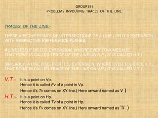
  • 1. TRACES OF THE LINE:- THESE ARE THE POINTS OF INTERSECTIONS OF A LINE ( OR IT’S EXTENSION ) WITH RESPECTIVE REFFERENCE PLANES. A LINE ITSELF OR IT’S EXTENSION, WHERE EVER TOUCHES H.P., THAT POINT IS CALLED TRACE OF THE LINE ON H.P.( IT IS CALLED H.T.) SIMILARLY, A LINE ITSELF OR IT’S EXTENSION, WHERE EVER TOUCHES V.P., THAT POINT IS CALLED TRACE OF THE LINE ON V.P.( IT IS CALLED V.T.) V.T.:- It is a point on Vp. Hence it is called Fv of a point in Vp. Hence it’s Tv comes on XY line.( Here onward named as v ) H.T.:- It is a point on Hp. Hence it is called Tv of a point in Hp. Hence it’s Fv comes on XY line.( Here onward named as ’h’ ) GROUP (B) PROBLEMS INVOLVING TRACES OF THE LINE.
  • 2. 1. Begin with FV. Extend FV up to XY line. 2. Name this point h’ ( as it is a Fv of a point in Hp) 3. Draw one projector from h’. 4. Now extend Tv to meet this projector. This point is HT STEPS TO LOCATE HT. (WHEN PROJECTIONS ARE GIVEN.) 1. Begin with TV. Extend TV up to XY line. 2. Name this point v ( as it is a Tv of a point in Vp) 3. Draw one projector from v. 4. Now extend Fv to meet this projector. This point is VT STEPS TO LOCATE VT. (WHEN PROJECTIONS ARE GIVEN.) h’ HTVT’ v a’ x y a b’ FV b TV Observe & note :- 1. Points h’ & v always on x-y line. 2. VT’ & v always on one projector. 3. HT & h’ always on one projector. 4. FV - h’- VT’ always co-linear. 5. TV - v - HT always co-linear. These points are used to solve next three problems.
  • 3. x y b’ b’1 a v VT’ a’ HT b h’ b1 ∅ 300 θ 450 PROBLEM 6 :- Fv of line AB makes 450 angle with XY line and measures 60 mm. Line’s Tv makes 300 with XY line. End A is 15 mm above Hp and it’s VT is 10 mm below Hp. Draw projections of line AB,determine inclinations with Hp & Vp and locate HT, VT. 15 10 SOLUTION STEPS:- Draw xy line, one projector and locate fv a’ 15 mm above xy. Take 450 angle from a’ and marking 60 mm on it locate point b’. Draw locus of VT, 10 mm below xy & extending Fv to this locus locate VT. as fv-h’-vt’ lie on one st.line. Draw projector from vt, locate v on xy. From v take 300 angle downward as Tv and it’s inclination can begin with v. Draw projector from b’ and locate b I.e.Tv point. Now rotating views as usual TL and it’s inclinations can be found. Name extension of Fv, touching xy as h’ and below it, on extension of Tv, locate HT.
  • 4. a’ b’ FV 30 45 10 LOCUS OF b’ & b’1 X Y 450 VT’ v HT h’ LOCUS OF b & b1 100 a b TV b’1 θ TL Φ TL b1 PROBLEM 7 : One end of line AB is 10mm above Hp and other end is 100 mm in-front of Vp. It’s Fv is 450 inclined to xy while it’s HT & VT are 45mm and 30 mm below xy respectively. Draw projections and find TL with it’s inclinations with Hp & VP. SOLUTION STEPS:- Draw xy line, one projector and locate a’ 10 mm above xy. Draw locus 100 mm below xy for points b & b1 Draw loci for VT and HT, 30 mm & 45 mm below xy respectively. Take 450 angle from a’ and extend that line backward to locate h’ and VT, & Locate v on xy above VT. Locate HT below h’ as shown. Then join v – HT – and extend to get top view end b. Draw projector upward and locate b’ Make a b & a’b’ dark. Now as usual rotating views find TL and it’s inclinations.
  • 5. X y HT VT h’ a’ v b’ a b 80 50 b’1 θ Φ TL TL FV TV b 1 10 35 55 Locus of a’ PROBLEM 8 :- Projectors drawn from HT and VT of a line AB are 80 mm apart and those drawn from it’s ends are 50 mm apart. End A is 10 mm above Hp, VT is 35 mm below Hp while it’s HT is 45 mm in front of Vp. Draw projections, locate traces and find TL of line & inclinations with Hp and Vp. SOLUTION STEPS:- 1.Draw xy line and two projectors, 80 mm apart and locate HT & VT , 35 mm below xy and 55 mm above xy respectively on these projectors. 2.Locate h’ and v on xy as usual. 3.Now just like previous two problems, Extending certain lines complete Fv & Tv And as usual find TL and it’s inclinations.
  • 6. b1 a’ FV VT’ v TV X Y b’ a b θ Φ b1’ TL TL Then from point v & HT angles can be drawn. & From point VT’ & h’ angles can be drawn.θα & Φβ & Instead of considering a & a’ as projections of first point, if v & VT’ are considered as first point , then true inclinations of line with Hp & Vp i.e. angles θ & Φ can be constructed with points VT’ & V respectively. THIS CONCEPT IS USED TO SOLVE NEXT THREE PROBLEMS.
  • 7. PROBLEM 9 :- Line AB 100 mm long is 300 and 450 inclined to Hp & Vp respectively. End A is 10 mm above Hp and it’s VT is 20 mm below Hp .Draw projections of the line and it’s HT. X Y VT’ v 10 20 Locus of a & a1’ θ (300 ) Φ(450 ) a1’ 100 mm b1’ b1 a1 100 mm b’ a’ b a FV TV HT h’ SOLUTION STEPS:- Draw xy, one projector and locate on it VT and V. Draw locus of a’ 10 mm above xy. Take 300 from VT and draw a line. Where it intersects with locus of a’ name it a1’ as it is TL of that part. From a1’ cut 100 mm (TL) on it and locate point b1’ Now from v take 450 and draw a line downwards & Mark on it distance VT-a1’ I.e.TL of extension & name it a1 Extend this line by 100 mm and mark point b1. Draw it’s component on locus of VT’ & further rotate to get other end of Fv i.e.b’ Join it with VT’ and mark intersection point (with locus of a1’ ) and name it a’ Now as usual locate points a and b and h’ and HT.
  • 8. PROBLEM 10 :- A line AB is 75 mm long. It’s Fv & Tv make 450 and 600 inclinations with X-Y line resp End A is 15 mm above Hp and VT is 20 mm below Xy line. Line is in first quadrant. Draw projections, find inclinations with Hp & Vp. Also locate HT. X Y VT’ v 15 20 Locus of a & a1’ a1’ 75 mm b1’ b1 a1 75 mm b’ a’ b a FV TV HT h’ 450 600 θ Φ SOLUTION STEPS:- Similar to the previous only change is instead of line’s inclinations, views inclinations are given. So first take those angles from VT & v Properly, construct Fv & Tv of extension, then determine it’s TL( V-a1) and on it’s extension mark TL of line and proceed and complete it.
  • 9. PROBLEM 11 :- The projectors drawn from VT & end A of line AB are 40mm apart. End A is 15mm above Hp and 25 mm in front of Vp. VT of line is 20 mm below Hp. If line is 75mm long, draw it’s projections, find inclinations with HP & Vp X Y 40mm 15 20 25 v VT’ a’ a a1’ b1’b’ b TV FV 75m m b1 θ Φ Draw two projectors for VT & end A Locate these points and then YES ! YOU CAN COMPLETE IT.
  • 10. X A.I.P. GROUP (C) CASES OF THE LINES IN A.V.P., A.I.P. & PROFILE PLANE. α αa’ b’ Line AB is in AIP as shown in above figure no 1. It’s FV (a’b’) is shown projected on Vp.(Looking in arrow direction) Here one can clearly see that the Inclination of AIP with HP = Inclination of FV with XY line Line AB is in AVP as shown in above figure no 2.. It’s TV (a b) is shown projected on Hp.(Looking in arrow direction) Here one can clearly see that the Inclination of AVP with VP = Inclination of TV with XY line A.V.P. β A B β a b B A
  • 11. PPVP HP a b a’ b’ a” b” X Y FV TV LSV A B a b a’ b’ For F.V. For T.V. LINE IN A PROFILE PLANE ( MEANS IN A PLANE PERPENDICULAR TO BOTH HP & VP) Results:- 1. TV & FV both are vertical, hence arrive on one single projector. 2. It’s Side View shows True Length ( TL) 3. Sum of it’s inclinations with HP & VP equals to 900 ( 4. It’s HT & VT arrive on same projector and can be easily located From Side View. θ Φ+ = 900 ) ORTHOGRAPHIC PATTERN OF LINE IN PROFILE PLANE HT VT θ Φ
  • 12. PROBLEM 12 :- Line AB 80 mm long, makes 300 angle with Hp and lies in an Aux.Vertical Plane 450 inclined to Vp. End A is 15 mm above Hp and VT is 10 mm below X-y line. Draw projections, fine angle with Vp and Ht. VT v X Y a b a’ b’ a1’ b1 ’ Locus of b’ Locus of b’ 10 15 HT h’ θ b1 Φ AVP 450 to VP 450 Locus of a’ & a1’ Simply consider inclination of AVP as inclination of TV of our line, well then? You sure can complete it as previous problems! Go ahead!!
  • 13. PROBLEM 13 :- A line AB, 75mm long, has one end A in Vp. Other end B is 15 mm above Hp and 50 mm in front of Vp.Draw the projections of the line when sum of it’s Inclinations with HP & Vp is 900 , means it is lying in a profile plane. Find true angles with ref.planes and it’s traces. a b HT VT X Y a’ b’ Side View ( True Length ) a” b” (HT) (VT) HP VP Front view top view SOLUTION STEPS:- After drawing xy line and one projector Locate top view of A I.e point a on xy as It is in Vp, Locate Fv of B i.e.b’15 mm above xy as it is above Hp.and Tv of B i.e. b, 50 mm below xy asit is 50 mm in front of Vp Draw side view structure of Vp and Hp and locate S.V. of point B i.e. b’’ From this point cut 75 mm distance on Vp and Mark a’’ as A is in Vp. (This is also VT of line.) From this point draw locus to left & get a’ Extend SV up to Hp. It will be HT. As it is a Tv Rotate it and bring it on projector of b. Now as discussed earlier SV gives TL of line and at the same time on extension up to Hp & Vp gives inclinations with those panes. θ Φ