
Recommandé
Contenu connexe
Similaire à Phase 2 - Task 1Task TypeDiscussion BoardDeliverable Length.docx
Similaire à Phase 2 - Task 1Task TypeDiscussion BoardDeliverable Length.docx (20)
Plus de randymartin91030
Plus de randymartin91030 (20)
Dernier
Dernier (20)
Phase 2 - Task 1Task TypeDiscussion BoardDeliverable Length.docx
- 1. Phase 2 - Task 1 Task Type: Discussion Board Deliverable Length: 400–600 words + 2 responses (100–200 words each) Points Possible: 75 Due Date: 1/18/2015 11:59:59 PM Primary Discussion Response is due by Wednesday (11:59:59pm Central), Peer Responses are due by Sunday (11:59:59pm Central). Primary Task Response: Within the Discussion Board area, write 400–600 words that respond to the following questions with your thoughts, ideas, and comments. This will be the foundation for future discussions with your classmates. Be substantive and clear, and use examples to reinforce your ideas. Library Research Assignment Translating detailed requirements into a design is the next very important step. An integrated set of computer-aided software engineering (CASE) tools can be very useful in modeling and documenting a software application or system. Investigate the library and Internet for information on at least 5 CASE tools such as unified modeling language (UML), functional decomposition diagrams, data flow diagrams, object diagrams, entity-relationship (E-R) diagrams, class diagrams, and structure charts. · Compare and contrast 5 of the CASE modeling tools by giving a brief description, including strengths and weaknesses. · Based on your research, which subset or individual CASE modeling tool or tools do you plan to use to develop the design for your project in this class, and why? Responses to Other Students: Respond to at least 2 of your
- 2. fellow classmates with a reply of 100–200 words about their Primary Task Response regarding items you found to be compelling and enlightening. To help you with your discussion, please consider the following questions: · What did you learn from your classmate's posting? · What additional questions do you have after reading the posting? · What clarification do you need regarding the posting? · What differences or similarities do you see between your posting and other classmates' postings? For assistance with your assignment, please use your text, Web resources, and all course materials. Course Materials Phase 2 - Task 2 Task Type: Individual Project Deliverable Length: 2–3 new pages Points Possible: 100 Due Date: 1/19/2015 11:59:59 PM Weekly tasks or assignments (Individual or Group Projects) will be due by Monday, and late submissions will be assigned a late penalty in accordance with the late penalty policy found in the syllabus. NOTE: All submission posting times are based on midnight Central Time. At this point, you are ready to execute the next phase in system development life cycle (SDLC), which is the design phase. Exploiting the research that you have performed in this week’s Discussion Board on the set of modeling tools, document the design for the application project that you selected.
- 3. Assignment For this assignment, you will use Visio Software Application to develop the design employing the following computer-aided software engineering (CASE) modeling tools: · Use case · Functional decomposition diagram · Entity-relationship (E-R) diagram, data flow diagram (DF), or class diagram · Sequence diagram · Mock-up or storyboard of the user interface screens The project deliverables are as follows: · Update the System Requirements, Design, and Implementation Specification title page with new date. · Update the previously completed sections based on the instructor's feedback. · System or Application Design · Develop a high-level use case to represent the application as a whole. · Develop a functional decomposition diagram to show all of the functions that the system or application will support. · Develop an E-R diagram, class diagram, or a data flow diagram that effectively represents the data that are required for your application or system. · Develop a sequence diagram to represent the timing of various activities within the application or system. · Develop a mock-up or storyboard for the high-level interface screens. · Name the document "yourname_IT425_IP2.doc." Please submit your assignment. For assistance with your assignment, please use your text, Web resources, and all course materials. Course Materials
- 4. Presentation Development Model Comparisons The following is a comparison of five computer-aided software engineering (CASE) diagrams, including their components and a description of their strengths and weakness: Use Case Diagram The use case diagram has the following components: · It uses cases to show the sequence of actions. · It shows actors, such as person, group, organization, or external system that play a role in interactions within the system. · Associations or communications represent interactions described by the model. · System boundaries show the area for functionality and scope. This diagram is described as a system or software development life cycle (SLDC) with defined phases. The diagram has the following strengths: · It provides a very high level of representation of the system or application as a whole, including scope. · Is a very good communication vehicle for capturing user requirements and communicating them to the users and stakeholders. The weakness of this diagram is that it requires other types of diagramming techniques to provide the drill-down detail. Object Diagrams The object diagram can be described as a rapid application development (RAD) that supports faster software development and uses a quick requirements-gathering phase. It goes into prototyping to further define requirements based upon user feedback on the prototype. The strength of this diagram is the time to market is greatly reduced for graphical user interface (GUI) or Web-based applications. Because it is so quick, proper testing is not always conducted. The prototypes are generally throw-away code. The Data Flow Diagrams
- 5. The data flow diagram (DFD) has the following components: · It uses squares or ovals to represent external entities, terminators, sources, or sink. · Circles or rounded rectangles represent processes within system. · Arrows represent data flows. · Open-ended rectangles represent data stores. Data flow diagrams illustrate the processes, data stores, and external entities in a system and the connecting data flows. Strengths of this model include the following: · It models real-world entities and methods. · It is excellent in supporting reuse. · It uses class diagrams to represent the model. To help the customers understand the requirements that they share, this model is complex to develop. Entity-Relationship Diagram The entity-relationship diagram (ERD) has the following components: · Entities represent objects in the real world. · Relationships represent connections between entities. · An associative object type indicator can represent both an object and a relationship. · The subtype and supertype indicator represent subcategories by a relationship. Entity-relationship diagrams are a form of a network model to represent the data within a system or application. Relationships show how data are represented by entities and logically related. The strength of this diagram shows the relationship between the various entities within a system. This diagram does not reflect sequence or activities within the system—only the data. Structure Charts The structure chart has the following components: · Boxes represent functions or modules. · Lines represent the linkage between functions and modules. This diagram is a top-down modular design that depicts
- 6. identifiable functions and the modules underneath or shows the functional decomposition. The strength of this diagram is to provide a way of decomposing an application or system into manageable modules. This diagram does not provide a lot of detail about the actual functions that will be performed in the system. Reference Techopedia. (2013) Unified modeling language (UML). Retrieved from http://www.techopedia.com/definition/3243/unified- modeling-language-uml Activity Computer-Aided Software Engineering Tools in the Development Process Click here to view a video defining computer-aided software engineering (CASE) tools and how they fit into the software life cycle development process. Reference Webb, P. (2009). Computer aided software engineering [Video]. Select Business Solution s. Retrieved from the YouTube Web site: http://www.youtube.com/watch?v=hHvypTnvF5E Activity Computer-Aided Software Engineering Tool Diagrams Click here to view a tutorial that starts with a use-case diagram and elaborates on it into activity, class, sequence, and
- 7. communication diagrams. This is a great initial tutorial to help understand the relationships of the various Unified Modeling Language (UML) diagrams. Reference Kench, E. (2009). UML tutorial [Video]. Retrieved from the YouTube Web site: http://www.youtube.com/watch?v=RMuMz5hQMf4 Activity UML Diagram Quiz Click on the Web links below for a set of two interactive quizzes that test UML knowledge. The user answers questions by dragging components to the various diagrams, and the quiz gives you real-time feedback and coaching if you get the wrong answer. The Home Page link gives you information on the site and the quizzes. The Quiz 1 and Quiz 2 links will take you to the respective quizzes. Reference The Open University. (2013). iCMA quizzes on UML diagrams. Retrieved from the OpenUniversity Web site:http://www.open.ac.uk/opencetl/centre-open-learning- mathematics-science-computing-and-technology/activities- projects/assessment/icma-quizzes-uml-diagrams
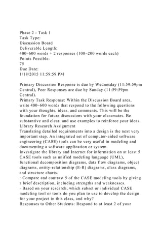
- 8. Activity Complete UML Tutorial Click here for a tutorial that provides a better understanding of Unified Modeling Language (UML). In addition to an overview, building blocks, and modeling types, there are tutorials that walk you through the creation of diagrams. These diagrams include: standard diagrams, class diagrams, object diagrams, component diagrams, deployment diagrams, use case diagrams, interaction diagrams, state chart diagrams, and activity diagrams. The various topics as well as the diagram tutorials can be accessed using the navigation bar on the left side of the Web site. Reference TutorialsPoint. (2013). UML tutorial. Retrieved from the TutorialsPoint Web site: http://www.tutorialspoint.com/uml/index.htm Article CASE Tool Environment Computer-aided software engineering (CASE) tools are a collection of software that is used to automate the various phases of the systems development life cycle (SDLC). The following image shows various classifications of CASE tools
- 9. that can be used together or separately. The CASE tool repository documentation and models are as follows: · Project management · Analysis and design · Modeling tools · Documentation tools · Prototyping tools · Coding support · Configuration management · Query and report generator · Backup and recovery · Export and import Article Sample Use Case Diagram The design phase of the system development life cycle (SDLC) necessitates translating the detailed requirements into a design. Computer-aided software engineering (CASE) tools are useful in modeling and documenting this phase. One such CASE tool is a use case diagram. The image shows an