SlideShare une entreprise Scribd logo
1  sur  23
E3145/3/1
PIPING AND INSTRUMENTATION DRAWING (PNID)
PIPING AND INSTRUMENTATION DRAWING
(PNID)
OBJECTIVES
General Objective : To understand and to apply the concept of piping and
instrumentation drawing (PNID).
Specific Objectives : At the end of the unit you will be able to :
 State the definition of PNID.
 Discuss the comparison between pneumatic control
system and hydraulic control system.
 Draw the instruments symbols.
 Name the symbols of pneumatic system components
and hydraulic system components.
UNIT3
E3145/3/2
PIPING AND INSTRUMENTATION DRAWING (PNID)
3.0 Explanation of PNID
Piping and instrumentation drawing (PNID) includes the components
of pneumatic control system and hydraulic control system. Pneumatic control
system uses compressible fluid meanwhile the hydraulic control system uses
incompressible fluid.
The basic components of pneumatic system are : compressor , air
tank, air dryer, regulator, directional control valve and actuator. For hydraulic
system the components are : pump, motor or cylinder, oil tank and valve.
Basically, pneumatic system is widely used in the electronic, food, and
automotive industry. Below are the uses of pneumatic system :
• Transferring of materials
• Drilling system
• Material handling (clamping, shifting, positioning, orienting)
• Stamping
• Packaging
• Automation
INPUTINPUT
Piping and instrumentation
drawing (PNID) includes the
components of pneumatic
control system and hydraulic
control system.
E3145/3/3
PIPING AND INSTRUMENTATION DRAWING (PNID)
Meanwhile, hydraulic system is normally used to operate :
• Back hoe
• Bull dozer
• CNC machine
• Load loader
• Die casting machine
The advantages of using pneumatic system and hydraulic system are
shown in Table 3.1 :
Pneumatic System Hydraulic System
1. Air – easy to get (unlimited). 1. Flexible – In power transmission ,
hydraulic power is more flexible
compared to pneumatic power.
2. Transmission – air is easy to
transfer for a long distance
through pipe line.
2. Force gain – a small force can be
used to control the large force.
3. Storage – compressed air can be
stored in air storage tank and
can be released if not needed.
3. Component – Does not need a lot
of moving mechanism.
4. Temperature – compressed air is
not sensitive to temperature
reactions that can cause burning.
4. Compact – hydraulic motor size is
smaller compared to electric
motor.
5. Clean – air leakage does not
cause environmental pollution.
5. Economy – hydraulic system is
better and more profit.
6. Component – pneumatic system
is easier to maintain and cheaper.
7. Speed – it can work faster than
hydraulic system.
8. It responses very fast to the start
and stop commands from the
controller.
9. Air does not need a back flow.
Table 3.1 : Advantages between pneumatic system and hydraulic system
E3145/3/4
PIPING AND INSTRUMENTATION DRAWING (PNID)
(Source : Jubaidi Bin Razali, Pneumatik & Hidraulik)
3.1 IDENTIFYING INSTRUMENTS SYMBOLS
3.1.1 Symbols of pneumatic component
The symbols of pneumatic components found in a pneumatic system are
shown below :
(Source : Jubaidi Bin Razali, Pneumatik & Hidraulik)
E3145/3/5
PIPING AND INSTRUMENTATION DRAWING (PNID)
(Source : Jubaidi Bin Razali, Pneumatik & Hidraulik)
E3145/3/6
PIPING AND INSTRUMENTATION DRAWING (PNID)
(Source : Jubaidi Bin Razali, Pneumatik & Hidraulik)
E3145/3/7
PIPING AND INSTRUMENTATION DRAWING (PNID)
(Source : Jubaidi Bin Razali, Pneumatik & Hidraulik)
E3145/3/8
PIPING AND INSTRUMENTATION DRAWING (PNID)
(Source : Jubaidi Bin Razali, Pneumatik & Hidraulik)
E3145/3/9
PIPING AND INSTRUMENTATION DRAWING (PNID)
3.1.2 Symbols of hydraulic component
The symbols of hydraulic components found in a hydraulic system are
shown below :
(Source : Jubaidi Bin Razali, Pneumatik & Hidraulik)
E3145/3/10
PIPING AND INSTRUMENTATION DRAWING (PNID)
(Source : Jubaidi Bin Razali, Pneumatik & Hidraulik)
E3145/3/11
PIPING AND INSTRUMENTATION DRAWING (PNID)
(Source : Jubaidi Bin Razali, Pneumatik & Hidraulik)
E3145/3/12
PIPING AND INSTRUMENTATION DRAWING (PNID)
(Source : Jubaidi Bin Razali, Pneumatik & Hidraulik)
E3145/3/13
PIPING AND INSTRUMENTATION DRAWING (PNID)
(Source : Jubaidi Bin Razali, Pneumatik & Hidraulik)
E3145/3/14
PIPING AND INSTRUMENTATION DRAWING (PNID)
(Source : Jubaidi Bin Razali, Pneumatik & Hidraulik)
E3145/3/15
PIPING AND INSTRUMENTATION DRAWING (PNID)
Activity 3
TEST YOUR UNDERSTANDING BEFORE YOU CONTINUE WITH THE
NEXT INPUT…!
3.1 Explain what is meant by Piping and Instrumentation Drawing (PNID)
3.2State the basic components of pneumatic system and hydraulic system.
3.3 State 5 components of pneumatic system and hydraulic system.
3.4 Give 3 industries that use pneumatic system.
E3145/3/16
PIPING AND INSTRUMENTATION DRAWING (PNID)
Feedback To Activity 3
3.1 Piping and instrumentation drawing (PNID) includes the components
of pneumatic control system and hydraulic control system. Pneumatic
control system uses a compressible fluid while the hydraulic control
system uses incompressible fluid.
3.2The basic components of pneumatic system are : compressor , air tank,
air dryer, regulator, directional control valve and actuator. The basic
components of hydraulic system are : tank, filter, pump, valve, motor
and cylinder.
3.3 Pneumatic system components
a. Pneumatic compressor
b. Pneumatic cylinder (single acting)
c. Pneumatic cylinder (double acting)
d. Valve 2/2
e. Flow controller valve
Hydraulic system components
a. Fixed displacement hydraulic pump
b. Double acting cylinder
c. Differential cylinder
d. Pneumatic motor
e. Direction controller valve 2/2 type
3.4 a. Food industry
b. Automotive industry
c. Electronic industry
E3145/3/17
PIPING AND INSTRUMENTATION DRAWING (PNID)
KEY FACTS
1. Piping and instrumentation drawing (PNID) includes :
• components of pneumatic control system
• components of hydraulic control system
2. The basic components of pneumatic system are :
• compressor
• air tank
• air dryer
• regulator
• directional control valve
• actuator
3. The basic components of hydraulic system are :
• pump
• motor or cylinder
• oil tank
• valve.
E3145/3/18
PIPING AND INSTRUMENTATION DRAWING (PNID)
SELF-ASSESSMENT
You are approaching success. Try all the questions in this self-assessment
section and check your answers with those given in the Feedback on Self-
Assessment given on the next page. If you face any problems, discuss it
with your lecturer. Good luck.
Q3-1 Define the word ‘PNEUMATIC’ and explain how this system functions.
Q3-2 State the advantages between pneumatic system and hydraulic
system.
Q3-3 State 5 advantages of pneumatic system.
Q3-4 Draw the symbols of the pneumatic components given below in the
space provided.
COMPONENT DESCRIPTION SYMBOLS
Pneumatic
compressor
Fixed displacement
Pneumatic
cylinder
(single acting)
Non-return spring
Spring return
E3145/3/19
PIPING AND INSTRUMENTATION DRAWING (PNID)
Pneumatic
cylinder
(double acting)
One rod
Two rod
2/2 valve
Closed loop double port
Open loop double port
E3145/3/20
PIPING AND INSTRUMENTATION DRAWING (PNID)
Feedback To Self-Assessment
Have you tried the questions????? If “YES”, check your answers now.
Q3-1 The word ‘Pneu’ is from Greece which means wind, ‘matic’ refers to
power. Therefore pneumatic system means a system which is
operated by wind. The pneumatic system uses compressed air as a
power transfer medium. The compressed air is obtained from the
environment. Then it is compressed using electric motor.
Q3-2
Pneumatic System Hydraulic System
1. Air – easy to get (unlimited). 1. Flexible – In power transmission ,
hydraulic power is more flexible
compared to pneumatic power.
2. Transmission – air is easy to
transfer for a long distance through
pipe line.
2. Force gain – a small force can be
used to control the large force.
3. Storage – compressed air can be
stored in air storage tank and can
be released if not needed.
3. Component – Does not need a lot
of moving mechanism.
E3145/3/21
PIPING AND INSTRUMENTATION DRAWING (PNID)
4. Temperature – compressed air is
not sensitive to temperature
reactions that can cause burning.
4. Compact – hydraulic motor size is
smaller compared to electric motor.
5. Clean – air leakage does not cause
environmental pollution.
5. Economy – hydraulic system is
better and more profit.
6. Component – pneumatic system is
easier to maintain and cheaper.
7. Speed – it can work faster than
hydraulic system.
8. It responses very fast to the start
and stop commands from the
controller.
9. Air does not need a back flow.
Q3-3 (Any five answers from this list are accepted)
1. Air – easy to get unlimited.
2. Transmission – air is easy to transfer for a long distance through pipe
line.
3. Storage – compressed air can be stored in air storage tank and can
be released if not needed.
4. Temperature – compressed air is not sensitive to temperature
reactions that can cause burning.
5. Clean – air leakage does not cause environmental pollution.
6. Component – pneumatic system is easier to maintain and cheaper.
7. Speed – it can work faster than hydraulic system
8. It responses very fast to the start and stop commands from the
controller.
9. Air does not need a back flow.
E3145/3/22
PIPING AND INSTRUMENTATION DRAWING (PNID)
Q3-4
E3145/3/23
PIPING AND INSTRUMENTATION DRAWING (PNID)

Contenu connexe

Tendances

Control system basics_open and closed loop control system
Control system basics_open and closed loop control systemControl system basics_open and closed loop control system
Control system basics_open and closed loop control systemNilesh Bhaskarrao Bahadure
 
Introduction to Control System Design
Introduction to Control System DesignIntroduction to Control System Design
Introduction to Control System DesignAndrew Wilhelm
 
Lecture2(introduction)
Lecture2(introduction)Lecture2(introduction)
Lecture2(introduction)Razali Tomari
 
Bag 1 pengenalan sistem kontrol
Bag 1 pengenalan sistem kontrolBag 1 pengenalan sistem kontrol
Bag 1 pengenalan sistem kontrolHIMTI
 
Introduction to control systems
Introduction to control systems Introduction to control systems
Introduction to control systems Hendi Saryanto
 
CSE-introduction about control system
CSE-introduction about control systemCSE-introduction about control system
CSE-introduction about control systemÐîgëñ Tàìlør
 
BEC 26 control-Systems_unit-I_pdf
BEC 26 control-Systems_unit-I_pdfBEC 26 control-Systems_unit-I_pdf
BEC 26 control-Systems_unit-I_pdfShadab Siddiqui
 
Pe 3032 wk 1 introduction to control system march 04e
Pe 3032 wk 1 introduction to control system  march 04ePe 3032 wk 1 introduction to control system  march 04e
Pe 3032 wk 1 introduction to control system march 04eCharlton Inao
 
218001 control system technology lecture 1
218001 control system technology   lecture 1218001 control system technology   lecture 1
218001 control system technology lecture 1Toàn Hữu
 
Control System Design
Control System DesignControl System Design
Control System DesignHitesh Sharma
 
Introduction to control system 2
Introduction to control system 2Introduction to control system 2
Introduction to control system 2turna67
 
Introduction to control system
Introduction to control systemIntroduction to control system
Introduction to control systemRosh54
 

Tendances (20)

Control system
Control systemControl system
Control system
 
Control system basics_open and closed loop control system
Control system basics_open and closed loop control systemControl system basics_open and closed loop control system
Control system basics_open and closed loop control system
 
Introduction to Control System Design
Introduction to Control System DesignIntroduction to Control System Design
Introduction to Control System Design
 
Lecture2(introduction)
Lecture2(introduction)Lecture2(introduction)
Lecture2(introduction)
 
Introduction to control systems
Introduction to control systemsIntroduction to control systems
Introduction to control systems
 
Lecture 1 the lecture
Lecture 1   the lectureLecture 1   the lecture
Lecture 1 the lecture
 
Cs unit-i-ii
Cs unit-i-iiCs unit-i-ii
Cs unit-i-ii
 
Bag 1 pengenalan sistem kontrol
Bag 1 pengenalan sistem kontrolBag 1 pengenalan sistem kontrol
Bag 1 pengenalan sistem kontrol
 
Introduction to control systems
Introduction to control systems Introduction to control systems
Introduction to control systems
 
Control system
Control systemControl system
Control system
 
CSE-introduction about control system
CSE-introduction about control systemCSE-introduction about control system
CSE-introduction about control system
 
BEC 26 control-Systems_unit-I_pdf
BEC 26 control-Systems_unit-I_pdfBEC 26 control-Systems_unit-I_pdf
BEC 26 control-Systems_unit-I_pdf
 
Pe 3032 wk 1 introduction to control system march 04e
Pe 3032 wk 1 introduction to control system  march 04ePe 3032 wk 1 introduction to control system  march 04e
Pe 3032 wk 1 introduction to control system march 04e
 
218001 control system technology lecture 1
218001 control system technology   lecture 1218001 control system technology   lecture 1
218001 control system technology lecture 1
 
Control System Design
Control System DesignControl System Design
Control System Design
 
Ppt on control system
Ppt on control systemPpt on control system
Ppt on control system
 
Basics of control system
Basics of control system Basics of control system
Basics of control system
 
Control system
Control systemControl system
Control system
 
Introduction to control system 2
Introduction to control system 2Introduction to control system 2
Introduction to control system 2
 
Introduction to control system
Introduction to control systemIntroduction to control system
Introduction to control system
 

En vedette

Basic Control System unit4
Basic Control System unit4Basic Control System unit4
Basic Control System unit4Asraf Malik
 
Basic Control System unit6
Basic Control System unit6Basic Control System unit6
Basic Control System unit6Asraf Malik
 
J4012 pneumatik dan hidraulik unit0
J4012 pneumatik dan hidraulik unit0J4012 pneumatik dan hidraulik unit0
J4012 pneumatik dan hidraulik unit0Asraf Malik
 
TIME DOMAIN ANALYSIS
TIME DOMAIN ANALYSISTIME DOMAIN ANALYSIS
TIME DOMAIN ANALYSISSyed Saeed
 
Time domain specifications of second order system
Time domain specifications of second order systemTime domain specifications of second order system
Time domain specifications of second order systemSyed Saeed
 
Time response second order
Time response second orderTime response second order
Time response second orderSyed Saeed
 
Performance of second order system
Performance of second order systemPerformance of second order system
Performance of second order systemTrupesh Rupareliya
 
Basic Control System unit0
Basic Control System unit0Basic Control System unit0
Basic Control System unit0Asraf Malik
 
ControlLogix Timers FA16
ControlLogix Timers FA16ControlLogix Timers FA16
ControlLogix Timers FA16John Todora
 
Pembuatan trainer input output mikroprosesor sebagai pengajaran praktik pener...
Pembuatan trainer input output mikroprosesor sebagai pengajaran praktik pener...Pembuatan trainer input output mikroprosesor sebagai pengajaran praktik pener...
Pembuatan trainer input output mikroprosesor sebagai pengajaran praktik pener...Miko Eljava
 
Pid standard note
Pid standard  notePid standard  note
Pid standard noteIPEC
 
JF608: Quality Control - Unit 2
JF608: Quality Control - Unit 2JF608: Quality Control - Unit 2
JF608: Quality Control - Unit 2Asraf Malik
 
TIME RESPONSE ANALYSIS
TIME RESPONSE ANALYSISTIME RESPONSE ANALYSIS
TIME RESPONSE ANALYSISSyed Saeed
 
Calculating the air-sea flux of any trace gas: transfer velocity, chemical e...
Calculating the air-sea flux of any trace gas:  transfer velocity, chemical e...Calculating the air-sea flux of any trace gas:  transfer velocity, chemical e...
Calculating the air-sea flux of any trace gas: transfer velocity, chemical e...Martin Johnson
 
Mechanical production of stirling Engine
Mechanical production of stirling EngineMechanical production of stirling Engine
Mechanical production of stirling EngineKum Visal
 
Time response analysis of system
Time response analysis of systemTime response analysis of system
Time response analysis of systemvishalgohel12195
 
E4141 sistem kawalan 1 unit4
E4141 sistem kawalan 1 unit4E4141 sistem kawalan 1 unit4
E4141 sistem kawalan 1 unit4Asraf Malik
 

En vedette (20)

Basic Control System unit4
Basic Control System unit4Basic Control System unit4
Basic Control System unit4
 
Basic Control System unit6
Basic Control System unit6Basic Control System unit6
Basic Control System unit6
 
J4012 pneumatik dan hidraulik unit0
J4012 pneumatik dan hidraulik unit0J4012 pneumatik dan hidraulik unit0
J4012 pneumatik dan hidraulik unit0
 
PJ Mechanical
PJ MechanicalPJ Mechanical
PJ Mechanical
 
TIME DOMAIN ANALYSIS
TIME DOMAIN ANALYSISTIME DOMAIN ANALYSIS
TIME DOMAIN ANALYSIS
 
Lab02 lead in
Lab02 lead inLab02 lead in
Lab02 lead in
 
Time domain specifications of second order system
Time domain specifications of second order systemTime domain specifications of second order system
Time domain specifications of second order system
 
Time response second order
Time response second orderTime response second order
Time response second order
 
Performance of second order system
Performance of second order systemPerformance of second order system
Performance of second order system
 
Basic Control System unit0
Basic Control System unit0Basic Control System unit0
Basic Control System unit0
 
ControlLogix Timers FA16
ControlLogix Timers FA16ControlLogix Timers FA16
ControlLogix Timers FA16
 
Pembuatan trainer input output mikroprosesor sebagai pengajaran praktik pener...
Pembuatan trainer input output mikroprosesor sebagai pengajaran praktik pener...Pembuatan trainer input output mikroprosesor sebagai pengajaran praktik pener...
Pembuatan trainer input output mikroprosesor sebagai pengajaran praktik pener...
 
Pid standard note
Pid standard  notePid standard  note
Pid standard note
 
JF608: Quality Control - Unit 2
JF608: Quality Control - Unit 2JF608: Quality Control - Unit 2
JF608: Quality Control - Unit 2
 
TIME RESPONSE ANALYSIS
TIME RESPONSE ANALYSISTIME RESPONSE ANALYSIS
TIME RESPONSE ANALYSIS
 
Calculating the air-sea flux of any trace gas: transfer velocity, chemical e...
Calculating the air-sea flux of any trace gas:  transfer velocity, chemical e...Calculating the air-sea flux of any trace gas:  transfer velocity, chemical e...
Calculating the air-sea flux of any trace gas: transfer velocity, chemical e...
 
Mechanical production of stirling Engine
Mechanical production of stirling EngineMechanical production of stirling Engine
Mechanical production of stirling Engine
 
Time response analysis of system
Time response analysis of systemTime response analysis of system
Time response analysis of system
 
Minggu3 pid
Minggu3 pidMinggu3 pid
Minggu3 pid
 
E4141 sistem kawalan 1 unit4
E4141 sistem kawalan 1 unit4E4141 sistem kawalan 1 unit4
E4141 sistem kawalan 1 unit4
 

Similaire à Basic Control System unit3

ME-6I-22655-UNIT-1-Shaikh-sir-Notes.pdf
ME-6I-22655-UNIT-1-Shaikh-sir-Notes.pdfME-6I-22655-UNIT-1-Shaikh-sir-Notes.pdf
ME-6I-22655-UNIT-1-Shaikh-sir-Notes.pdfDEEPAKKUMARD4
 
Introduction to Pneumatic Systems
Introduction to Pneumatic SystemsIntroduction to Pneumatic Systems
Introduction to Pneumatic SystemsRAHUL THAKER
 
Topic 3 - Working Principles.pptx
Topic 3 - Working Principles.pptxTopic 3 - Working Principles.pptx
Topic 3 - Working Principles.pptxDieniesTorres
 
Pneumatic circuits
Pneumatic circuitsPneumatic circuits
Pneumatic circuitsRAHUL THAKER
 
Design and Optimization of Air Compressor Intake Valve Body Casing using ANSYS
Design and Optimization of Air Compressor Intake Valve Body Casing using ANSYSDesign and Optimization of Air Compressor Intake Valve Body Casing using ANSYS
Design and Optimization of Air Compressor Intake Valve Body Casing using ANSYSIRJET Journal
 
Pneumatic Shearing and Bending Machine
Pneumatic Shearing and Bending MachinePneumatic Shearing and Bending Machine
Pneumatic Shearing and Bending Machinepaperpublications3
 
Pu Hall Calculations_2
Pu Hall Calculations_2Pu Hall Calculations_2
Pu Hall Calculations_2fraz mirza
 
PLC OPERATED AIR COMPRESSED ENGINE
PLC OPERATED AIR COMPRESSED ENGINEPLC OPERATED AIR COMPRESSED ENGINE
PLC OPERATED AIR COMPRESSED ENGINEIRJET Journal
 
Efficient speed governor for blower motor
Efficient speed governor for blower motorEfficient speed governor for blower motor
Efficient speed governor for blower motoreSAT Publishing House
 
Efficient speed governor for blower motor
Efficient speed governor for blower motorEfficient speed governor for blower motor
Efficient speed governor for blower motoreSAT Journals
 
IRJET- Material Removal Rate (MRR) Study in Time Reduction Pneumatic Shaper M...
IRJET- Material Removal Rate (MRR) Study in Time Reduction Pneumatic Shaper M...IRJET- Material Removal Rate (MRR) Study in Time Reduction Pneumatic Shaper M...
IRJET- Material Removal Rate (MRR) Study in Time Reduction Pneumatic Shaper M...IRJET Journal
 
IRJET- Static Structural and Modal Analysis of Secondary Air Flow System
IRJET- Static Structural and Modal Analysis of Secondary Air Flow SystemIRJET- Static Structural and Modal Analysis of Secondary Air Flow System
IRJET- Static Structural and Modal Analysis of Secondary Air Flow SystemIRJET Journal
 
PNEUMATIC CUP SEALER
PNEUMATIC CUP SEALERPNEUMATIC CUP SEALER
PNEUMATIC CUP SEALERIRJET Journal
 

Similaire à Basic Control System unit3 (20)

ME-6I-22655-UNIT-1-Shaikh-sir-Notes.pdf
ME-6I-22655-UNIT-1-Shaikh-sir-Notes.pdfME-6I-22655-UNIT-1-Shaikh-sir-Notes.pdf
ME-6I-22655-UNIT-1-Shaikh-sir-Notes.pdf
 
Pneumatic systems
Pneumatic systemsPneumatic systems
Pneumatic systems
 
Introduction to Pneumatic Systems
Introduction to Pneumatic SystemsIntroduction to Pneumatic Systems
Introduction to Pneumatic Systems
 
Topic 3 - Working Principles.pptx
Topic 3 - Working Principles.pptxTopic 3 - Working Principles.pptx
Topic 3 - Working Principles.pptx
 
E1303041923
E1303041923E1303041923
E1303041923
 
Pneumatic circuits
Pneumatic circuitsPneumatic circuits
Pneumatic circuits
 
Design and Optimization of Air Compressor Intake Valve Body Casing using ANSYS
Design and Optimization of Air Compressor Intake Valve Body Casing using ANSYSDesign and Optimization of Air Compressor Intake Valve Body Casing using ANSYS
Design and Optimization of Air Compressor Intake Valve Body Casing using ANSYS
 
Pneumatic Shearing and Bending Machine
Pneumatic Shearing and Bending MachinePneumatic Shearing and Bending Machine
Pneumatic Shearing and Bending Machine
 
Pu Hall Calculations_2
Pu Hall Calculations_2Pu Hall Calculations_2
Pu Hall Calculations_2
 
Automation 4.0
Automation 4.0Automation 4.0
Automation 4.0
 
Pneumatic System
Pneumatic SystemPneumatic System
Pneumatic System
 
PLC OPERATED AIR COMPRESSED ENGINE
PLC OPERATED AIR COMPRESSED ENGINEPLC OPERATED AIR COMPRESSED ENGINE
PLC OPERATED AIR COMPRESSED ENGINE
 
Efficient speed governor for blower motor
Efficient speed governor for blower motorEfficient speed governor for blower motor
Efficient speed governor for blower motor
 
Efficient speed governor for blower motor
Efficient speed governor for blower motorEfficient speed governor for blower motor
Efficient speed governor for blower motor
 
IRJET- Material Removal Rate (MRR) Study in Time Reduction Pneumatic Shaper M...
IRJET- Material Removal Rate (MRR) Study in Time Reduction Pneumatic Shaper M...IRJET- Material Removal Rate (MRR) Study in Time Reduction Pneumatic Shaper M...
IRJET- Material Removal Rate (MRR) Study in Time Reduction Pneumatic Shaper M...
 
IRJET- Static Structural and Modal Analysis of Secondary Air Flow System
IRJET- Static Structural and Modal Analysis of Secondary Air Flow SystemIRJET- Static Structural and Modal Analysis of Secondary Air Flow System
IRJET- Static Structural and Modal Analysis of Secondary Air Flow System
 
PNEUMATIC SHAPER MACHINE
PNEUMATIC SHAPER MACHINEPNEUMATIC SHAPER MACHINE
PNEUMATIC SHAPER MACHINE
 
30120140507005
3012014050700530120140507005
30120140507005
 
30120140507005
3012014050700530120140507005
30120140507005
 
PNEUMATIC CUP SEALER
PNEUMATIC CUP SEALERPNEUMATIC CUP SEALER
PNEUMATIC CUP SEALER
 

Plus de Asraf Malik

JF608: Quality Control - Unit 6
JF608: Quality Control - Unit 6JF608: Quality Control - Unit 6
JF608: Quality Control - Unit 6Asraf Malik
 
JF608: Quality Control - Unit 5
JF608: Quality Control - Unit 5JF608: Quality Control - Unit 5
JF608: Quality Control - Unit 5Asraf Malik
 
Mechanical Component and Maintenance
Mechanical Component and MaintenanceMechanical Component and Maintenance
Mechanical Component and MaintenanceAsraf Malik
 
JF608: Quality Control - Unit 4
JF608: Quality Control - Unit 4JF608: Quality Control - Unit 4
JF608: Quality Control - Unit 4Asraf Malik
 
JF608: Quality Control - Unit 3
JF608: Quality Control - Unit 3JF608: Quality Control - Unit 3
JF608: Quality Control - Unit 3Asraf Malik
 
JF608: Quality Control - Unit 1
JF608: Quality Control - Unit 1JF608: Quality Control - Unit 1
JF608: Quality Control - Unit 1Asraf Malik
 
MATERIAL TECHNOLOGY - CHAPTER 7
MATERIAL TECHNOLOGY  - CHAPTER 7MATERIAL TECHNOLOGY  - CHAPTER 7
MATERIAL TECHNOLOGY - CHAPTER 7Asraf Malik
 
MATERIAL TECHNOLOGY - CHAPTER 8
MATERIAL TECHNOLOGY - CHAPTER 8MATERIAL TECHNOLOGY - CHAPTER 8
MATERIAL TECHNOLOGY - CHAPTER 8Asraf Malik
 
MATERIAL TECHNOLOGY 2 - CHAPTER 6
MATERIAL TECHNOLOGY 2 - CHAPTER 6MATERIAL TECHNOLOGY 2 - CHAPTER 6
MATERIAL TECHNOLOGY 2 - CHAPTER 6Asraf Malik
 
MATERIAL TECHNOLOGY : CHAPTER 5
MATERIAL TECHNOLOGY : CHAPTER 5MATERIAL TECHNOLOGY : CHAPTER 5
MATERIAL TECHNOLOGY : CHAPTER 5Asraf Malik
 
MATERIAL TECHNOLOGY 1: CHAPTER 4
MATERIAL TECHNOLOGY 1: CHAPTER 4MATERIAL TECHNOLOGY 1: CHAPTER 4
MATERIAL TECHNOLOGY 1: CHAPTER 4Asraf Malik
 
JF302: Material Technology, Chapter 3
JF302: Material Technology, Chapter 3JF302: Material Technology, Chapter 3
JF302: Material Technology, Chapter 3Asraf Malik
 
Material Technology: Chapter 2
Material Technology: Chapter 2Material Technology: Chapter 2
Material Technology: Chapter 2Asraf Malik
 
JF302 Material Technology: Chapter 1
JF302 Material Technology: Chapter 1JF302 Material Technology: Chapter 1
JF302 Material Technology: Chapter 1Asraf Malik
 
Workshop Technology 2, Chapter 6
Workshop Technology 2, Chapter 6Workshop Technology 2, Chapter 6
Workshop Technology 2, Chapter 6Asraf Malik
 
Workshop Technology 2, Chapter 5
Workshop Technology 2, Chapter 5Workshop Technology 2, Chapter 5
Workshop Technology 2, Chapter 5Asraf Malik
 
Workshop Technology, Chapter 4
Workshop Technology, Chapter 4Workshop Technology, Chapter 4
Workshop Technology, Chapter 4Asraf Malik
 
Workshop Technology 2, Chapter 3
Workshop Technology 2, Chapter 3Workshop Technology 2, Chapter 3
Workshop Technology 2, Chapter 3Asraf Malik
 
Workshop Technology 2, Chapter 2
Workshop Technology 2, Chapter 2Workshop Technology 2, Chapter 2
Workshop Technology 2, Chapter 2Asraf Malik
 
Workshop Technology 2, Chapter 1
Workshop Technology 2, Chapter 1Workshop Technology 2, Chapter 1
Workshop Technology 2, Chapter 1Asraf Malik
 

Plus de Asraf Malik (20)

JF608: Quality Control - Unit 6
JF608: Quality Control - Unit 6JF608: Quality Control - Unit 6
JF608: Quality Control - Unit 6
 
JF608: Quality Control - Unit 5
JF608: Quality Control - Unit 5JF608: Quality Control - Unit 5
JF608: Quality Control - Unit 5
 
Mechanical Component and Maintenance
Mechanical Component and MaintenanceMechanical Component and Maintenance
Mechanical Component and Maintenance
 
JF608: Quality Control - Unit 4
JF608: Quality Control - Unit 4JF608: Quality Control - Unit 4
JF608: Quality Control - Unit 4
 
JF608: Quality Control - Unit 3
JF608: Quality Control - Unit 3JF608: Quality Control - Unit 3
JF608: Quality Control - Unit 3
 
JF608: Quality Control - Unit 1
JF608: Quality Control - Unit 1JF608: Quality Control - Unit 1
JF608: Quality Control - Unit 1
 
MATERIAL TECHNOLOGY - CHAPTER 7
MATERIAL TECHNOLOGY  - CHAPTER 7MATERIAL TECHNOLOGY  - CHAPTER 7
MATERIAL TECHNOLOGY - CHAPTER 7
 
MATERIAL TECHNOLOGY - CHAPTER 8
MATERIAL TECHNOLOGY - CHAPTER 8MATERIAL TECHNOLOGY - CHAPTER 8
MATERIAL TECHNOLOGY - CHAPTER 8
 
MATERIAL TECHNOLOGY 2 - CHAPTER 6
MATERIAL TECHNOLOGY 2 - CHAPTER 6MATERIAL TECHNOLOGY 2 - CHAPTER 6
MATERIAL TECHNOLOGY 2 - CHAPTER 6
 
MATERIAL TECHNOLOGY : CHAPTER 5
MATERIAL TECHNOLOGY : CHAPTER 5MATERIAL TECHNOLOGY : CHAPTER 5
MATERIAL TECHNOLOGY : CHAPTER 5
 
MATERIAL TECHNOLOGY 1: CHAPTER 4
MATERIAL TECHNOLOGY 1: CHAPTER 4MATERIAL TECHNOLOGY 1: CHAPTER 4
MATERIAL TECHNOLOGY 1: CHAPTER 4
 
JF302: Material Technology, Chapter 3
JF302: Material Technology, Chapter 3JF302: Material Technology, Chapter 3
JF302: Material Technology, Chapter 3
 
Material Technology: Chapter 2
Material Technology: Chapter 2Material Technology: Chapter 2
Material Technology: Chapter 2
 
JF302 Material Technology: Chapter 1
JF302 Material Technology: Chapter 1JF302 Material Technology: Chapter 1
JF302 Material Technology: Chapter 1
 
Workshop Technology 2, Chapter 6
Workshop Technology 2, Chapter 6Workshop Technology 2, Chapter 6
Workshop Technology 2, Chapter 6
 
Workshop Technology 2, Chapter 5
Workshop Technology 2, Chapter 5Workshop Technology 2, Chapter 5
Workshop Technology 2, Chapter 5
 
Workshop Technology, Chapter 4
Workshop Technology, Chapter 4Workshop Technology, Chapter 4
Workshop Technology, Chapter 4
 
Workshop Technology 2, Chapter 3
Workshop Technology 2, Chapter 3Workshop Technology 2, Chapter 3
Workshop Technology 2, Chapter 3
 
Workshop Technology 2, Chapter 2
Workshop Technology 2, Chapter 2Workshop Technology 2, Chapter 2
Workshop Technology 2, Chapter 2
 
Workshop Technology 2, Chapter 1
Workshop Technology 2, Chapter 1Workshop Technology 2, Chapter 1
Workshop Technology 2, Chapter 1
 

Dernier

The Most Excellent Way | 1 Corinthians 13
The Most Excellent Way | 1 Corinthians 13The Most Excellent Way | 1 Corinthians 13
The Most Excellent Way | 1 Corinthians 13Steve Thomason
 
General AI for Medical Educators April 2024
General AI for Medical Educators April 2024General AI for Medical Educators April 2024
General AI for Medical Educators April 2024Janet Corral
 
fourth grading exam for kindergarten in writing
fourth grading exam for kindergarten in writingfourth grading exam for kindergarten in writing
fourth grading exam for kindergarten in writingTeacherCyreneCayanan
 
Advanced Views - Calendar View in Odoo 17
Advanced Views - Calendar View in Odoo 17Advanced Views - Calendar View in Odoo 17
Advanced Views - Calendar View in Odoo 17Celine George
 
A Critique of the Proposed National Education Policy Reform
A Critique of the Proposed National Education Policy ReformA Critique of the Proposed National Education Policy Reform
A Critique of the Proposed National Education Policy ReformChameera Dedduwage
 
Sanyam Choudhary Chemistry practical.pdf
Sanyam Choudhary Chemistry practical.pdfSanyam Choudhary Chemistry practical.pdf
Sanyam Choudhary Chemistry practical.pdfsanyamsingh5019
 
Accessible design: Minimum effort, maximum impact
Accessible design: Minimum effort, maximum impactAccessible design: Minimum effort, maximum impact
Accessible design: Minimum effort, maximum impactdawncurless
 
Arihant handbook biology for class 11 .pdf
Arihant handbook biology for class 11 .pdfArihant handbook biology for class 11 .pdf
Arihant handbook biology for class 11 .pdfchloefrazer622
 
Holdier Curriculum Vitae (April 2024).pdf
Holdier Curriculum Vitae (April 2024).pdfHoldier Curriculum Vitae (April 2024).pdf
Holdier Curriculum Vitae (April 2024).pdfagholdier
 
Interactive Powerpoint_How to Master effective communication
Interactive Powerpoint_How to Master effective communicationInteractive Powerpoint_How to Master effective communication
Interactive Powerpoint_How to Master effective communicationnomboosow
 
Call Girls in Dwarka Mor Delhi Contact Us 9654467111
Call Girls in Dwarka Mor Delhi Contact Us 9654467111Call Girls in Dwarka Mor Delhi Contact Us 9654467111
Call Girls in Dwarka Mor Delhi Contact Us 9654467111Sapana Sha
 
Measures of Dispersion and Variability: Range, QD, AD and SD
Measures of Dispersion and Variability: Range, QD, AD and SDMeasures of Dispersion and Variability: Range, QD, AD and SD
Measures of Dispersion and Variability: Range, QD, AD and SDThiyagu K
 
Ecosystem Interactions Class Discussion Presentation in Blue Green Lined Styl...
Ecosystem Interactions Class Discussion Presentation in Blue Green Lined Styl...Ecosystem Interactions Class Discussion Presentation in Blue Green Lined Styl...
Ecosystem Interactions Class Discussion Presentation in Blue Green Lined Styl...fonyou31
 
Kisan Call Centre - To harness potential of ICT in Agriculture by answer farm...
Kisan Call Centre - To harness potential of ICT in Agriculture by answer farm...Kisan Call Centre - To harness potential of ICT in Agriculture by answer farm...
Kisan Call Centre - To harness potential of ICT in Agriculture by answer farm...Krashi Coaching
 
Software Engineering Methodologies (overview)
Software Engineering Methodologies (overview)Software Engineering Methodologies (overview)
Software Engineering Methodologies (overview)eniolaolutunde
 
Explore beautiful and ugly buildings. Mathematics helps us create beautiful d...
Explore beautiful and ugly buildings. Mathematics helps us create beautiful d...Explore beautiful and ugly buildings. Mathematics helps us create beautiful d...
Explore beautiful and ugly buildings. Mathematics helps us create beautiful d...christianmathematics
 
Nutritional Needs Presentation - HLTH 104
Nutritional Needs Presentation - HLTH 104Nutritional Needs Presentation - HLTH 104
Nutritional Needs Presentation - HLTH 104misteraugie
 
The basics of sentences session 2pptx copy.pptx
The basics of sentences session 2pptx copy.pptxThe basics of sentences session 2pptx copy.pptx
The basics of sentences session 2pptx copy.pptxheathfieldcps1
 
Unit-IV- Pharma. Marketing Channels.pptx
Unit-IV- Pharma. Marketing Channels.pptxUnit-IV- Pharma. Marketing Channels.pptx
Unit-IV- Pharma. Marketing Channels.pptxVishalSingh1417
 
Class 11th Physics NEET formula sheet pdf
Class 11th Physics NEET formula sheet pdfClass 11th Physics NEET formula sheet pdf
Class 11th Physics NEET formula sheet pdfAyushMahapatra5
 

Dernier (20)

The Most Excellent Way | 1 Corinthians 13
The Most Excellent Way | 1 Corinthians 13The Most Excellent Way | 1 Corinthians 13
The Most Excellent Way | 1 Corinthians 13
 
General AI for Medical Educators April 2024
General AI for Medical Educators April 2024General AI for Medical Educators April 2024
General AI for Medical Educators April 2024
 
fourth grading exam for kindergarten in writing
fourth grading exam for kindergarten in writingfourth grading exam for kindergarten in writing
fourth grading exam for kindergarten in writing
 
Advanced Views - Calendar View in Odoo 17
Advanced Views - Calendar View in Odoo 17Advanced Views - Calendar View in Odoo 17
Advanced Views - Calendar View in Odoo 17
 
A Critique of the Proposed National Education Policy Reform
A Critique of the Proposed National Education Policy ReformA Critique of the Proposed National Education Policy Reform
A Critique of the Proposed National Education Policy Reform
 
Sanyam Choudhary Chemistry practical.pdf
Sanyam Choudhary Chemistry practical.pdfSanyam Choudhary Chemistry practical.pdf
Sanyam Choudhary Chemistry practical.pdf
 
Accessible design: Minimum effort, maximum impact
Accessible design: Minimum effort, maximum impactAccessible design: Minimum effort, maximum impact
Accessible design: Minimum effort, maximum impact
 
Arihant handbook biology for class 11 .pdf
Arihant handbook biology for class 11 .pdfArihant handbook biology for class 11 .pdf
Arihant handbook biology for class 11 .pdf
 
Holdier Curriculum Vitae (April 2024).pdf
Holdier Curriculum Vitae (April 2024).pdfHoldier Curriculum Vitae (April 2024).pdf
Holdier Curriculum Vitae (April 2024).pdf
 
Interactive Powerpoint_How to Master effective communication
Interactive Powerpoint_How to Master effective communicationInteractive Powerpoint_How to Master effective communication
Interactive Powerpoint_How to Master effective communication
 
Call Girls in Dwarka Mor Delhi Contact Us 9654467111
Call Girls in Dwarka Mor Delhi Contact Us 9654467111Call Girls in Dwarka Mor Delhi Contact Us 9654467111
Call Girls in Dwarka Mor Delhi Contact Us 9654467111
 
Measures of Dispersion and Variability: Range, QD, AD and SD
Measures of Dispersion and Variability: Range, QD, AD and SDMeasures of Dispersion and Variability: Range, QD, AD and SD
Measures of Dispersion and Variability: Range, QD, AD and SD
 
Ecosystem Interactions Class Discussion Presentation in Blue Green Lined Styl...
Ecosystem Interactions Class Discussion Presentation in Blue Green Lined Styl...Ecosystem Interactions Class Discussion Presentation in Blue Green Lined Styl...
Ecosystem Interactions Class Discussion Presentation in Blue Green Lined Styl...
 
Kisan Call Centre - To harness potential of ICT in Agriculture by answer farm...
Kisan Call Centre - To harness potential of ICT in Agriculture by answer farm...Kisan Call Centre - To harness potential of ICT in Agriculture by answer farm...
Kisan Call Centre - To harness potential of ICT in Agriculture by answer farm...
 
Software Engineering Methodologies (overview)
Software Engineering Methodologies (overview)Software Engineering Methodologies (overview)
Software Engineering Methodologies (overview)
 
Explore beautiful and ugly buildings. Mathematics helps us create beautiful d...
Explore beautiful and ugly buildings. Mathematics helps us create beautiful d...Explore beautiful and ugly buildings. Mathematics helps us create beautiful d...
Explore beautiful and ugly buildings. Mathematics helps us create beautiful d...
 
Nutritional Needs Presentation - HLTH 104
Nutritional Needs Presentation - HLTH 104Nutritional Needs Presentation - HLTH 104
Nutritional Needs Presentation - HLTH 104
 
The basics of sentences session 2pptx copy.pptx
The basics of sentences session 2pptx copy.pptxThe basics of sentences session 2pptx copy.pptx
The basics of sentences session 2pptx copy.pptx
 
Unit-IV- Pharma. Marketing Channels.pptx
Unit-IV- Pharma. Marketing Channels.pptxUnit-IV- Pharma. Marketing Channels.pptx
Unit-IV- Pharma. Marketing Channels.pptx
 
Class 11th Physics NEET formula sheet pdf
Class 11th Physics NEET formula sheet pdfClass 11th Physics NEET formula sheet pdf
Class 11th Physics NEET formula sheet pdf
 

Basic Control System unit3

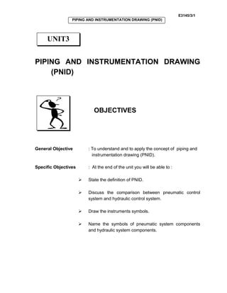
  • 1. E3145/3/1 PIPING AND INSTRUMENTATION DRAWING (PNID) PIPING AND INSTRUMENTATION DRAWING (PNID) OBJECTIVES General Objective : To understand and to apply the concept of piping and instrumentation drawing (PNID). Specific Objectives : At the end of the unit you will be able to :  State the definition of PNID.  Discuss the comparison between pneumatic control system and hydraulic control system.  Draw the instruments symbols.  Name the symbols of pneumatic system components and hydraulic system components. UNIT3
  • 2. E3145/3/2 PIPING AND INSTRUMENTATION DRAWING (PNID) 3.0 Explanation of PNID Piping and instrumentation drawing (PNID) includes the components of pneumatic control system and hydraulic control system. Pneumatic control system uses compressible fluid meanwhile the hydraulic control system uses incompressible fluid. The basic components of pneumatic system are : compressor , air tank, air dryer, regulator, directional control valve and actuator. For hydraulic system the components are : pump, motor or cylinder, oil tank and valve. Basically, pneumatic system is widely used in the electronic, food, and automotive industry. Below are the uses of pneumatic system : • Transferring of materials • Drilling system • Material handling (clamping, shifting, positioning, orienting) • Stamping • Packaging • Automation INPUTINPUT Piping and instrumentation drawing (PNID) includes the components of pneumatic control system and hydraulic control system.
  • 3. E3145/3/3 PIPING AND INSTRUMENTATION DRAWING (PNID) Meanwhile, hydraulic system is normally used to operate : • Back hoe • Bull dozer • CNC machine • Load loader • Die casting machine The advantages of using pneumatic system and hydraulic system are shown in Table 3.1 : Pneumatic System Hydraulic System 1. Air – easy to get (unlimited). 1. Flexible – In power transmission , hydraulic power is more flexible compared to pneumatic power. 2. Transmission – air is easy to transfer for a long distance through pipe line. 2. Force gain – a small force can be used to control the large force. 3. Storage – compressed air can be stored in air storage tank and can be released if not needed. 3. Component – Does not need a lot of moving mechanism. 4. Temperature – compressed air is not sensitive to temperature reactions that can cause burning. 4. Compact – hydraulic motor size is smaller compared to electric motor. 5. Clean – air leakage does not cause environmental pollution. 5. Economy – hydraulic system is better and more profit. 6. Component – pneumatic system is easier to maintain and cheaper. 7. Speed – it can work faster than hydraulic system. 8. It responses very fast to the start and stop commands from the controller. 9. Air does not need a back flow. Table 3.1 : Advantages between pneumatic system and hydraulic system
  • 4. E3145/3/4 PIPING AND INSTRUMENTATION DRAWING (PNID) (Source : Jubaidi Bin Razali, Pneumatik & Hidraulik) 3.1 IDENTIFYING INSTRUMENTS SYMBOLS 3.1.1 Symbols of pneumatic component The symbols of pneumatic components found in a pneumatic system are shown below : (Source : Jubaidi Bin Razali, Pneumatik & Hidraulik)
  • 5. E3145/3/5 PIPING AND INSTRUMENTATION DRAWING (PNID) (Source : Jubaidi Bin Razali, Pneumatik & Hidraulik)
  • 6. E3145/3/6 PIPING AND INSTRUMENTATION DRAWING (PNID) (Source : Jubaidi Bin Razali, Pneumatik & Hidraulik)
  • 7. E3145/3/7 PIPING AND INSTRUMENTATION DRAWING (PNID) (Source : Jubaidi Bin Razali, Pneumatik & Hidraulik)
  • 8. E3145/3/8 PIPING AND INSTRUMENTATION DRAWING (PNID) (Source : Jubaidi Bin Razali, Pneumatik & Hidraulik)
  • 9. E3145/3/9 PIPING AND INSTRUMENTATION DRAWING (PNID) 3.1.2 Symbols of hydraulic component The symbols of hydraulic components found in a hydraulic system are shown below : (Source : Jubaidi Bin Razali, Pneumatik & Hidraulik)
  • 10. E3145/3/10 PIPING AND INSTRUMENTATION DRAWING (PNID) (Source : Jubaidi Bin Razali, Pneumatik & Hidraulik)
  • 11. E3145/3/11 PIPING AND INSTRUMENTATION DRAWING (PNID) (Source : Jubaidi Bin Razali, Pneumatik & Hidraulik)
  • 12. E3145/3/12 PIPING AND INSTRUMENTATION DRAWING (PNID) (Source : Jubaidi Bin Razali, Pneumatik & Hidraulik)
  • 13. E3145/3/13 PIPING AND INSTRUMENTATION DRAWING (PNID) (Source : Jubaidi Bin Razali, Pneumatik & Hidraulik)
  • 14. E3145/3/14 PIPING AND INSTRUMENTATION DRAWING (PNID) (Source : Jubaidi Bin Razali, Pneumatik & Hidraulik)
  • 15. E3145/3/15 PIPING AND INSTRUMENTATION DRAWING (PNID) Activity 3 TEST YOUR UNDERSTANDING BEFORE YOU CONTINUE WITH THE NEXT INPUT…! 3.1 Explain what is meant by Piping and Instrumentation Drawing (PNID) 3.2State the basic components of pneumatic system and hydraulic system. 3.3 State 5 components of pneumatic system and hydraulic system. 3.4 Give 3 industries that use pneumatic system.
  • 16. E3145/3/16 PIPING AND INSTRUMENTATION DRAWING (PNID) Feedback To Activity 3 3.1 Piping and instrumentation drawing (PNID) includes the components of pneumatic control system and hydraulic control system. Pneumatic control system uses a compressible fluid while the hydraulic control system uses incompressible fluid. 3.2The basic components of pneumatic system are : compressor , air tank, air dryer, regulator, directional control valve and actuator. The basic components of hydraulic system are : tank, filter, pump, valve, motor and cylinder. 3.3 Pneumatic system components a. Pneumatic compressor b. Pneumatic cylinder (single acting) c. Pneumatic cylinder (double acting) d. Valve 2/2 e. Flow controller valve Hydraulic system components a. Fixed displacement hydraulic pump b. Double acting cylinder c. Differential cylinder d. Pneumatic motor e. Direction controller valve 2/2 type 3.4 a. Food industry b. Automotive industry c. Electronic industry
  • 17. E3145/3/17 PIPING AND INSTRUMENTATION DRAWING (PNID) KEY FACTS 1. Piping and instrumentation drawing (PNID) includes : • components of pneumatic control system • components of hydraulic control system 2. The basic components of pneumatic system are : • compressor • air tank • air dryer • regulator • directional control valve • actuator 3. The basic components of hydraulic system are : • pump • motor or cylinder • oil tank • valve.
  • 18. E3145/3/18 PIPING AND INSTRUMENTATION DRAWING (PNID) SELF-ASSESSMENT You are approaching success. Try all the questions in this self-assessment section and check your answers with those given in the Feedback on Self- Assessment given on the next page. If you face any problems, discuss it with your lecturer. Good luck. Q3-1 Define the word ‘PNEUMATIC’ and explain how this system functions. Q3-2 State the advantages between pneumatic system and hydraulic system. Q3-3 State 5 advantages of pneumatic system. Q3-4 Draw the symbols of the pneumatic components given below in the space provided. COMPONENT DESCRIPTION SYMBOLS Pneumatic compressor Fixed displacement Pneumatic cylinder (single acting) Non-return spring Spring return
  • 19. E3145/3/19 PIPING AND INSTRUMENTATION DRAWING (PNID) Pneumatic cylinder (double acting) One rod Two rod 2/2 valve Closed loop double port Open loop double port
  • 20. E3145/3/20 PIPING AND INSTRUMENTATION DRAWING (PNID) Feedback To Self-Assessment Have you tried the questions????? If “YES”, check your answers now. Q3-1 The word ‘Pneu’ is from Greece which means wind, ‘matic’ refers to power. Therefore pneumatic system means a system which is operated by wind. The pneumatic system uses compressed air as a power transfer medium. The compressed air is obtained from the environment. Then it is compressed using electric motor. Q3-2 Pneumatic System Hydraulic System 1. Air – easy to get (unlimited). 1. Flexible – In power transmission , hydraulic power is more flexible compared to pneumatic power. 2. Transmission – air is easy to transfer for a long distance through pipe line. 2. Force gain – a small force can be used to control the large force. 3. Storage – compressed air can be stored in air storage tank and can be released if not needed. 3. Component – Does not need a lot of moving mechanism.
  • 21. E3145/3/21 PIPING AND INSTRUMENTATION DRAWING (PNID) 4. Temperature – compressed air is not sensitive to temperature reactions that can cause burning. 4. Compact – hydraulic motor size is smaller compared to electric motor. 5. Clean – air leakage does not cause environmental pollution. 5. Economy – hydraulic system is better and more profit. 6. Component – pneumatic system is easier to maintain and cheaper. 7. Speed – it can work faster than hydraulic system. 8. It responses very fast to the start and stop commands from the controller. 9. Air does not need a back flow. Q3-3 (Any five answers from this list are accepted) 1. Air – easy to get unlimited. 2. Transmission – air is easy to transfer for a long distance through pipe line. 3. Storage – compressed air can be stored in air storage tank and can be released if not needed. 4. Temperature – compressed air is not sensitive to temperature reactions that can cause burning. 5. Clean – air leakage does not cause environmental pollution. 6. Component – pneumatic system is easier to maintain and cheaper. 7. Speed – it can work faster than hydraulic system 8. It responses very fast to the start and stop commands from the controller. 9. Air does not need a back flow.