SlideShare une entreprise Scribd logo
1  sur  4
Télécharger pour lire hors ligne
© 2013 UTC Fire & Security. All rights reserved. 1 / 4 P/N 3101074 • REV 05 • REB 25JAN13
B4U Analog Standard Detector Base
Installation Sheet
EN FR
EN: Installation Sheet
Description
The B4U Analog Standard Detector Base provides mounting
support and electrical connections for the compatible detectors
listed in "Specifications.”
The base does not require a separate address.
The base comes with an adaptor bracket and trim ring for use
with a 4 in. square electrical box.
Installation
There are two ways to install the B4U base assembly.
• Option 1: Use an octagon or single-gang electrical box.
• Option 2: Use a 4 in. square electrical box.
To install the B4U using option 1:
1. Install an octagon or single-gang electrical box.
2. Pull the wiring into the box and through the hole in the
center of the detector base.
3. Attach the detector base to the electrical box, using the
screws provided with the electrical box.
4. Make wiring connections as shown in Figure 3.
5. Apply power and activate the unit to verify that it is
operating.
Figure 1: Base installation option 1
2
3
1
1. Octagonal electrical box
2. B4U base assembly
3. Screws
To install the B4U using option 2:
1. Install a 4 in. square electrical box.
2. Pull the wiring into the box and mount the adapter bracket
that comes with the B4U.
3. Pull the wires through the hole in the detector base and
attach the detector base to the electrical box, using the
adaptor bracket and the screws provided with the
electrical box. See Figure 2.
4. Attach the trim ring by aligning the arrows on the trim ring
with those on the base, and pressing down to lock the trim
ring into place.
5. Make wiring connections as shown in Figure 3.
6. Apply power and activate the unit to verify that it is
operating.
Note: Attaching the trim ring to the detector can occur before
or after assembling the detector to the base.
2 / 4 P/N 3101074 • REV 05 • REB 25JAN13
Figure 2: Base installation option 2
1
3
4
5
2
6
2
1. 4 in. square electrical box
2. Adaptor bracket
3. B4U base assembly
4 Screws
5. Trim ring
6. Aligning arrows
Wiring
Wire in accordance with NFPA 72 or CAN/ULC-S524. Be sure
to observe the polarity of the terminals on the terminal block as
shown in the diagram.
Break the wire run at each terminal. Do not loop signaling
circuit field wires around terminals.
Caution: To avoid accidental damage to the panel, disconnect
all power before wiring the unit.
Note: If shielded cable is used, the following recommendations
apply:
• Shielded wire is required only in environments with very
high electrical noise.
• Use of shield connections must be continuous and must
be insulated from ground. Electrical tape is recommended
as a minimum to insulate the shield.
• For Class B wiring, all shields must be continuous and
insulated from ground, except at the originating panel.
Figure 3: Base wiring (option 2 installation shown)
1
3
2
4
5
6
1
2
5
1. From previous device or controller
2. Optional trim ring
3. Optional bracket
4. Maximum resistance per wire must not exceed 10 Ω
5. To next device
Terminal Description Terminal Description
1 SLC in + and
SLC out (+)
4 Not used
2 SLC in − 5 Remote LED +
3 Not used 6 Remote LED −
and SLC out −
Specifications
Base diameter
Without trim ring
With trim ring
4.35 in. (110.49 mm)
6.0 in. (152 mm)
Height from box (including
detector)
2.08 in. (53 mm)
Maximum distance
Ceiling
Wall
Not less than 4 in. (100 mm) from the
sidewall
Between 4 and 12 in. (100 and
300 mm) from the ceiling
Wire size 12 to 18 AWG wire (0.75 to 2.5 mm²)
Compatible detectors FX-PD, E-PD, FX-PHD, E-PHD,
FX-HD, E-HD, V-PS, V-PHS, V-HRD,
and V-HFD
Compatible electrical boxes 4 × 4 in. octagonal ring (mud box)
1-7/8 in. (47 mm) deep single-gang
box
4 in. square x 2-1/2 in. (64 mm) deep
box (requires using the included
adaptor bracket and trim ring)
Operating environment
Temperature
Relative humidity
32 to 120°F (0 to 49°C)
0 to 93% noncondensing
Storage temperature range −4 to 140°F (−20 to 60°C)
P/N 3101074 • REV 05 • REB 25JAN13 3 / 4
Regulatory information
Manufacturer Edwards, A Division of UTC Fire & Security Americas
Corporation, Inc.
8985 Town Center Parkway, Bradenton, FL 34202,
USA
Year of
manufacture
The first two digits of the date code (located on the
product identification label) are the year of
manufacture
North
American
standards
FCC Part 15, Subpart J, Class B; DOC, Class/MDC
Class B. UL 268, UL 521, CAN/ULC-S529-09,
CAN/ULC-S530-M91
Contact information
For contact information, see our Web site:
www.edwardsutcfs.com.
FR : Fiche D'Installation
Description
La base analogique standard B4U pour détecteur fonctionne
avec les détecteurs compatibles répertoriés à la section
« Fiche technique ».
La base n'exige pas une adresse séparée.
La base vient avec une parenthèse d'adapteur et un anneau
d'équilibre pour l'usage avec les 4 po. boîte électrique carrée.
Installation
Il y a deux manières d'installer le montage bas de B4U.
• Option 1 : Utilisez une boîte électrique d'octogone ou de
simple-troupe.
• Option 2 : Utilisez une boîte électrique qui est 4 po. carré.
Pour installer le B4U utilisant l'option 1 :
1. Installez une boîte électrique d'octogone ou de simple-
troupe.
2. Tirez le câblage dans la boîte et par le trou au centre de la
base de détecteur.
3. Attachez la base de détecteur dans la boîte électrique,
utilisant les vis fournies par la boîte électrique.
4. Établissez les rapports de câblage suivant les indications
du Figure 3.
5. Activez la base pour vérifier qu'elle fonctionne.
Figure 1 : Option 1 d’installation de la base
2
3
1
1. Boîte électrique octogonale
2. La base de B4U
3. Vis
Pour installer le B4U utilisant l'option 2 :
1. Installez une boîte électrique qui est 4 po. carré.
2. Tirez le câblage dans la boîte et par la parenthèse
d'adapteur qui vient avec le B4U.
3. Attachez la base de détecteur dans la boîte électrique,
utilisant la parenthèse d'adapteur et les vis fournies par la
boîte électrique. Voir la Figure 2.
4. Alignez les marques sur l’anneau de garniture avec celles
de la plaque de la base, pressez l’anneau dans la plaque
et faites pivoter l’anneau jusqu’à ce qu’elle se verrouille en
place.
5. Établissez les rapports de câblage suivant les indications
du Figure 3.
6. Activez la base pour vérifier qu'elle fonctionne.
Figure 2 : Option 2 d’installation de la base
1
3
4
5
2
6
2
1. Flèches de alignement
2. Parenthèse facultative
3. Boîte carrée de 10 cm (4 po)
4. La base de B4U
5. Vis
6. Anneau facultatif d'équilibre
4 / 4 P/N 3101074 • REV 05 • REB 25JAN13
Remarque : La fixation de l'anneau d'équilibre au détecteur
peut se produire avant ou après assembler le détecteur à la
base.
Filage
Câblez conformément aux normes NFPA 72 et
CAN/ULC-S524. Assurez-vous de bien observer la polarité des
bornes sur le bornier, tel qu’indiqué sur le diagramme.
Interrompez le filage à chacune des bornes. Ne faites pas de
boucle autour des bornes avec les câbles du champ du circuit
de signalisation.
Avertissement : Pour éviter tout dommage accidentel au
panneau, débranchez toute alimentation électrique avant de
câbler le dispositif.
Remarque : Recommandations à suivre si vous utilisez un
câble armé :
• Un fil blindé est requis UNIQUEMENT dans les
environnements à interférences électriques élevées.
• Le blindage doit être continu et isolé de la terre. La bande
électrique est recommandée comme minimum pour isoler
le bouclier.
• Pour le câblage de la classe B, tous les boucliers doivent
être continus et isolés de la terre, à moins qu'au panneau
d'origine.
Figure 3 : Câblage de la base
1
3
2
4
5
6
1
2
5
1. Du dispositif ou du contrôleur précédent
2. La résistance maximum par fil ne doit pas dépasser 10 Ω
3. Au prochain dispositif
4. Parenthèse facultative
5. Anneau facultatif d'équilibre
Borne Description Borne Description
1 Entrée SLC + et sortie SLC + 4 Non utilisé
2 Entrée SLC − 5 DEL à distance +
3 Non utilisé 6 DEL à distance − et
sortie SLC −
Fiche technique
Diamètre de la base
sans la plaque de base
avec la plaque de la base
110.49 mm (4.35 po.)
152 mm (6 po.)
Hauteur à partir du coffret
(détecteur inclus)
53 mm (2.08 po.)
Distance maximale
montage du plafond
montage mural
Pas moins que 100 mm (4 po.) du
mur lateral
Entre 100 et 300 mm (4 et 12 po.) du
plafond
Dimensions du câble Câbles de 12 à 18 AWG (0.75 à
2.5 mm2
)
Détecteurs compatibles FX-PD, E-PD, FX-PHD, E-PHD,
FX-HD, E-HD, V-PS, V-PHS, V-HRD
et V-HFD
Coffrets électriques
compatibles
Anneau octogonal de 10 x 10 cm
(4 x 4 po.) (boîte à boue)
Coffret de 47 mm de profond
Coffret carrée de 10 cm (4 po.) x
64 mm (2.5 po.) de profond (exige
utilisant la parenthèse d'adapteur et
l'anneau d'équilibre qui sont inclus)
Cadre opérationnel
Température
Plage d’humidité relative
0 à 4°C (32 à 12°F)
0 à 93 sans condensation
Plage de la température
d’entreposage
−20 à 60°C (−4 à 140°F)
Référencement des agences
Fabricant Edwards, A Division of UTC Fire & Security
Americas Corporation, Inc.
8985 Town Center Parkway, Bradenton, FL 34202,
USA
L’année de
fabrication
Les deux premiers chiffres du code de date (situé
sur l'étiquette d'identification de produit) sont
l'année de la fabrication
Normes nord-
américaines
FCC Part 15, Subpart J, Class B, DOC Class/MDC
Class B. UL 268, UL 521, CAN/ULC-S529-09,
CAN/ULC-S530-M91
Coordonnées
Pour obtenir nos coordonnées, consultez le site Web
www.edwardsutcfs.com.

Contenu connexe

Tendances

Manuel Stylstar Fr
Manuel Stylstar FrManuel Stylstar Fr
Manuel Stylstar Frguest8a1c5d
 
La motorisation d'un portail à verrine
La motorisation d'un portail à verrineLa motorisation d'un portail à verrine
La motorisation d'un portail à verrineGENICIMO
 
Rvl480 Siemens présentation sommaire
Rvl480 Siemens présentation sommaireRvl480 Siemens présentation sommaire
Rvl480 Siemens présentation sommairee-genieclimatique
 
Windows and fixed glazing, thermally insulated - ISO fineline fitting product...
Windows and fixed glazing, thermally insulated - ISO fineline fitting product...Windows and fixed glazing, thermally insulated - ISO fineline fitting product...
Windows and fixed glazing, thermally insulated - ISO fineline fitting product...Rp Technik Australia
 
Réussir la pose des piliers et portail
Réussir la pose des piliers et portailRéussir la pose des piliers et portail
Réussir la pose des piliers et portailGENICIMO
 
Rvp351 instructions d_installation_fr
Rvp351 instructions d_installation_frRvp351 instructions d_installation_fr
Rvp351 instructions d_installation_fre-genieclimatique
 
Réussir votre installation électrique
Réussir votre installation électriqueRéussir votre installation électrique
Réussir votre installation électriquezakarianho10
 

Tendances (12)

Manuel Stylstar Fr
Manuel Stylstar FrManuel Stylstar Fr
Manuel Stylstar Fr
 
TECHNOLOGIE
TECHNOLOGIETECHNOLOGIE
TECHNOLOGIE
 
La motorisation d'un portail à verrine
La motorisation d'un portail à verrineLa motorisation d'un portail à verrine
La motorisation d'un portail à verrine
 
Manual GCE-X-4VR
Manual GCE-X-4VRManual GCE-X-4VR
Manual GCE-X-4VR
 
Rvl480 Siemens présentation sommaire
Rvl480 Siemens présentation sommaireRvl480 Siemens présentation sommaire
Rvl480 Siemens présentation sommaire
 
Windows and fixed glazing, thermally insulated - ISO fineline fitting product...
Windows and fixed glazing, thermally insulated - ISO fineline fitting product...Windows and fixed glazing, thermally insulated - ISO fineline fitting product...
Windows and fixed glazing, thermally insulated - ISO fineline fitting product...
 
Sqk33.00 fiche produit_fr
Sqk33.00 fiche produit_frSqk33.00 fiche produit_fr
Sqk33.00 fiche produit_fr
 
Réussir la pose des piliers et portail
Réussir la pose des piliers et portailRéussir la pose des piliers et portail
Réussir la pose des piliers et portail
 
Rvp351 instructions d_installation_fr
Rvp351 instructions d_installation_frRvp351 instructions d_installation_fr
Rvp351 instructions d_installation_fr
 
Réussir votre installation électrique
Réussir votre installation électriqueRéussir votre installation électrique
Réussir votre installation électrique
 
Seh62.1 fiche produit_fr
Seh62.1 fiche produit_frSeh62.1 fiche produit_fr
Seh62.1 fiche produit_fr
 
Sez 61.5
Sez 61.5Sez 61.5
Sez 61.5
 

En vedette

C12 perla gomez_ortega
C12 perla gomez_ortegaC12 perla gomez_ortega
C12 perla gomez_ortegaperlart
 
COMO ESCOLHER QUAL O DESTINO DAS PRÓXIMAS FÉRIAS
COMO ESCOLHER QUAL O DESTINO DAS PRÓXIMAS FÉRIASCOMO ESCOLHER QUAL O DESTINO DAS PRÓXIMAS FÉRIAS
COMO ESCOLHER QUAL O DESTINO DAS PRÓXIMAS FÉRIASViaje Mais Pagando Menos
 
dan elliott resume july 14 2015
dan elliott resume july 14 2015 dan elliott resume july 14 2015
dan elliott resume july 14 2015 Dan Elliott
 
¿Pero qué me estás diciendo?
¿Pero qué me estás diciendo?¿Pero qué me estás diciendo?
¿Pero qué me estás diciendo?kathajzak
 
Andrew Grigg Resume
Andrew Grigg ResumeAndrew Grigg Resume
Andrew Grigg ResumeAndy Grigg
 
данилевский
данилевскийданилевский
данилевскийzhmenchuk
 
Casos de leitura ar, er, ir, or, ur[1]
Casos de leitura ar, er, ir, or, ur[1]Casos de leitura ar, er, ir, or, ur[1]
Casos de leitura ar, er, ir, or, ur[1]mariacarmcorreia
 

En vedette (14)

C12 perla gomez_ortega
C12 perla gomez_ortegaC12 perla gomez_ortega
C12 perla gomez_ortega
 
My anthology
My anthologyMy anthology
My anthology
 
COMO ESCOLHER QUAL O DESTINO DAS PRÓXIMAS FÉRIAS
COMO ESCOLHER QUAL O DESTINO DAS PRÓXIMAS FÉRIASCOMO ESCOLHER QUAL O DESTINO DAS PRÓXIMAS FÉRIAS
COMO ESCOLHER QUAL O DESTINO DAS PRÓXIMAS FÉRIAS
 
Ingles
InglesIngles
Ingles
 
dan elliott resume july 14 2015
dan elliott resume july 14 2015 dan elliott resume july 14 2015
dan elliott resume july 14 2015
 
¿Pero qué me estás diciendo?
¿Pero qué me estás diciendo?¿Pero qué me estás diciendo?
¿Pero qué me estás diciendo?
 
Andrew Grigg Resume
Andrew Grigg ResumeAndrew Grigg Resume
Andrew Grigg Resume
 
данилевский
данилевскийданилевский
данилевский
 
Resume
ResumeResume
Resume
 
Certificate ADVANCE
Certificate ADVANCECertificate ADVANCE
Certificate ADVANCE
 
RES-Resume
RES-ResumeRES-Resume
RES-Resume
 
Acota2
Acota2Acota2
Acota2
 
Acota vistas 2
Acota vistas 2Acota vistas 2
Acota vistas 2
 
Casos de leitura ar, er, ir, or, ur[1]
Casos de leitura ar, er, ir, or, ur[1]Casos de leitura ar, er, ir, or, ur[1]
Casos de leitura ar, er, ir, or, ur[1]
 

Similaire à Edwards Signaling B4U Installation Manual

Edwards Signaling WG4RF-HVMHC Installation Manual
Edwards Signaling WG4RF-HVMHC Installation ManualEdwards Signaling WG4RF-HVMHC Installation Manual
Edwards Signaling WG4RF-HVMHC Installation ManualJMAC Supply
 
Detnov ccd 112 manual-t
Detnov ccd 112 manual-tDetnov ccd 112 manual-t
Detnov ccd 112 manual-tjelogon
 
Manuel Stylstar Fr
Manuel Stylstar FrManuel Stylstar Fr
Manuel Stylstar Frguest8a1c5d
 
Manuel Stylstar Fr
Manuel Stylstar FrManuel Stylstar Fr
Manuel Stylstar Frguest8a1c5d
 
Etude d'un Join Box. Comment choisir un bon joint pour le déploiement de son ...
Etude d'un Join Box. Comment choisir un bon joint pour le déploiement de son ...Etude d'un Join Box. Comment choisir un bon joint pour le déploiement de son ...
Etude d'un Join Box. Comment choisir un bon joint pour le déploiement de son ...MalekBienvenu
 
3 cft tile (li-tile) - Servicio Tecnico Fagor
3 cft tile (li-tile) - Servicio Tecnico Fagor3 cft tile (li-tile) - Servicio Tecnico Fagor
3 cft tile (li-tile) - Servicio Tecnico Fagorserviciotecnicofagor
 
Lehmannaudio Black Cube Statement manual - 5 languages
Lehmannaudio Black Cube Statement manual - 5 languagesLehmannaudio Black Cube Statement manual - 5 languages
Lehmannaudio Black Cube Statement manual - 5 languagesNorbert Lehmann
 
Catalogues produits 04: accessoires et câblage
Catalogues produits 04: accessoires et câblageCatalogues produits 04: accessoires et câblage
Catalogues produits 04: accessoires et câblageLAUMAS
 
Installation_Electriques_Domestiques_2010_FR_LR.pdf
Installation_Electriques_Domestiques_2010_FR_LR.pdfInstallation_Electriques_Domestiques_2010_FR_LR.pdf
Installation_Electriques_Domestiques_2010_FR_LR.pdfIonutCatalin8
 
Ecosense Slim Cove INT Installation Guide
Ecosense Slim Cove INT Installation GuideEcosense Slim Cove INT Installation Guide
Ecosense Slim Cove INT Installation Guidevalorlighting
 
Lehmannaudio Black Cube /Black Cube SE manual - 5 languages
Lehmannaudio Black Cube /Black Cube SE manual - 5 languagesLehmannaudio Black Cube /Black Cube SE manual - 5 languages
Lehmannaudio Black Cube /Black Cube SE manual - 5 languagesNorbert Lehmann
 
Acome connector data sheets - Acome liitinesitteet
Acome connector data sheets - Acome liitinesitteetAcome connector data sheets - Acome liitinesitteet
Acome connector data sheets - Acome liitinesitteetAerial Oy
 
Edwards Signaling 89STRB-AQ Installation Manual
Edwards Signaling 89STRB-AQ Installation ManualEdwards Signaling 89STRB-AQ Installation Manual
Edwards Signaling 89STRB-AQ Installation ManualJMAC Supply
 
Le circuit électrique apparent
Le circuit électrique apparentLe circuit électrique apparent
Le circuit électrique apparentGENICIMO
 
Notice - BEAM ALLIANCE
Notice - BEAM ALLIANCENotice - BEAM ALLIANCE
Notice - BEAM ALLIANCEHomexity
 
Amphenol_Push_Pull_12_2017_V2.0.pdf
Amphenol_Push_Pull_12_2017_V2.0.pdfAmphenol_Push_Pull_12_2017_V2.0.pdf
Amphenol_Push_Pull_12_2017_V2.0.pdfPierreChoquenet
 
Presentation resotel legrand RESOTEL
Presentation resotel legrand RESOTELPresentation resotel legrand RESOTEL
Presentation resotel legrand RESOTELAchille Enone
 
Fiche Technique Boite d'extrémté INES MAX
Fiche Technique Boite d'extrémté INES MAX Fiche Technique Boite d'extrémté INES MAX
Fiche Technique Boite d'extrémté INES MAX Amzil Yassine
 
Audifonos inalambricos
Audifonos inalambricosAudifonos inalambricos
Audifonos inalambricosJFM2612
 

Similaire à Edwards Signaling B4U Installation Manual (20)

Edwards Signaling WG4RF-HVMHC Installation Manual
Edwards Signaling WG4RF-HVMHC Installation ManualEdwards Signaling WG4RF-HVMHC Installation Manual
Edwards Signaling WG4RF-HVMHC Installation Manual
 
Detnov ccd 112 manual-t
Detnov ccd 112 manual-tDetnov ccd 112 manual-t
Detnov ccd 112 manual-t
 
Manuel Stylstar Fr
Manuel Stylstar FrManuel Stylstar Fr
Manuel Stylstar Fr
 
Manuel Stylstar Fr
Manuel Stylstar FrManuel Stylstar Fr
Manuel Stylstar Fr
 
Etude d'un Join Box. Comment choisir un bon joint pour le déploiement de son ...
Etude d'un Join Box. Comment choisir un bon joint pour le déploiement de son ...Etude d'un Join Box. Comment choisir un bon joint pour le déploiement de son ...
Etude d'un Join Box. Comment choisir un bon joint pour le déploiement de son ...
 
3 cft tile (li-tile) - Servicio Tecnico Fagor
3 cft tile (li-tile) - Servicio Tecnico Fagor3 cft tile (li-tile) - Servicio Tecnico Fagor
3 cft tile (li-tile) - Servicio Tecnico Fagor
 
Analyseur
AnalyseurAnalyseur
Analyseur
 
Lehmannaudio Black Cube Statement manual - 5 languages
Lehmannaudio Black Cube Statement manual - 5 languagesLehmannaudio Black Cube Statement manual - 5 languages
Lehmannaudio Black Cube Statement manual - 5 languages
 
Catalogues produits 04: accessoires et câblage
Catalogues produits 04: accessoires et câblageCatalogues produits 04: accessoires et câblage
Catalogues produits 04: accessoires et câblage
 
Installation_Electriques_Domestiques_2010_FR_LR.pdf
Installation_Electriques_Domestiques_2010_FR_LR.pdfInstallation_Electriques_Domestiques_2010_FR_LR.pdf
Installation_Electriques_Domestiques_2010_FR_LR.pdf
 
Ecosense Slim Cove INT Installation Guide
Ecosense Slim Cove INT Installation GuideEcosense Slim Cove INT Installation Guide
Ecosense Slim Cove INT Installation Guide
 
Lehmannaudio Black Cube /Black Cube SE manual - 5 languages
Lehmannaudio Black Cube /Black Cube SE manual - 5 languagesLehmannaudio Black Cube /Black Cube SE manual - 5 languages
Lehmannaudio Black Cube /Black Cube SE manual - 5 languages
 
Acome connector data sheets - Acome liitinesitteet
Acome connector data sheets - Acome liitinesitteetAcome connector data sheets - Acome liitinesitteet
Acome connector data sheets - Acome liitinesitteet
 
Edwards Signaling 89STRB-AQ Installation Manual
Edwards Signaling 89STRB-AQ Installation ManualEdwards Signaling 89STRB-AQ Installation Manual
Edwards Signaling 89STRB-AQ Installation Manual
 
Le circuit électrique apparent
Le circuit électrique apparentLe circuit électrique apparent
Le circuit électrique apparent
 
Notice - BEAM ALLIANCE
Notice - BEAM ALLIANCENotice - BEAM ALLIANCE
Notice - BEAM ALLIANCE
 
Amphenol_Push_Pull_12_2017_V2.0.pdf
Amphenol_Push_Pull_12_2017_V2.0.pdfAmphenol_Push_Pull_12_2017_V2.0.pdf
Amphenol_Push_Pull_12_2017_V2.0.pdf
 
Presentation resotel legrand RESOTEL
Presentation resotel legrand RESOTELPresentation resotel legrand RESOTEL
Presentation resotel legrand RESOTEL
 
Fiche Technique Boite d'extrémté INES MAX
Fiche Technique Boite d'extrémté INES MAX Fiche Technique Boite d'extrémté INES MAX
Fiche Technique Boite d'extrémté INES MAX
 
Audifonos inalambricos
Audifonos inalambricosAudifonos inalambricos
Audifonos inalambricos
 

Plus de JMAC Supply

Bosch ALTV244UL Data Sheet
Bosch ALTV244UL Data SheetBosch ALTV244UL Data Sheet
Bosch ALTV244UL Data SheetJMAC Supply
 
Bosch AL1002WAL Data Sheet
Bosch AL1002WAL Data SheetBosch AL1002WAL Data Sheet
Bosch AL1002WAL Data SheetJMAC Supply
 
Bosch AIM-AEC21-CVT Data Sheet
Bosch AIM-AEC21-CVT Data SheetBosch AIM-AEC21-CVT Data Sheet
Bosch AIM-AEC21-CVT Data SheetJMAC Supply
 
Bosch AI1 Data Sheet
Bosch AI1 Data SheetBosch AI1 Data Sheet
Bosch AI1 Data SheetJMAC Supply
 
Bosch AH-24WP-R Data Sheet
Bosch AH-24WP-R Data SheetBosch AH-24WP-R Data Sheet
Bosch AH-24WP-R Data SheetJMAC Supply
 
Bosch AEC-8I8O-EXT Data Sheet
Bosch AEC-8I8O-EXT Data SheetBosch AEC-8I8O-EXT Data Sheet
Bosch AEC-8I8O-EXT Data SheetJMAC Supply
 
Bosch AE774 Data Sheet
Bosch AE774 Data SheetBosch AE774 Data Sheet
Bosch AE774 Data SheetJMAC Supply
 
Bosch AE203R Data Sheet
Bosch AE203R Data SheetBosch AE203R Data Sheet
Bosch AE203R Data SheetJMAC Supply
 
Bosch AE101 Data Sheet
Bosch AE101 Data SheetBosch AE101 Data Sheet
Bosch AE101 Data SheetJMAC Supply
 
Bosch AE4 Data Sheet
Bosch AE4 Data SheetBosch AE4 Data Sheet
Bosch AE4 Data SheetJMAC Supply
 
Bosch AE1 Data Sheet
Bosch AE1 Data SheetBosch AE1 Data Sheet
Bosch AE1 Data SheetJMAC Supply
 
Bosch ACD-IC16K37-50 Data Sheet
Bosch ACD-IC16K37-50 Data SheetBosch ACD-IC16K37-50 Data Sheet
Bosch ACD-IC16K37-50 Data SheetJMAC Supply
 
Bosch ACD-IC2K37-50 Data Sheet
Bosch ACD-IC2K37-50 Data SheetBosch ACD-IC2K37-50 Data Sheet
Bosch ACD-IC2K37-50 Data SheetJMAC Supply
 
Bosch ACA-IC2K26-10 Data Sheet
Bosch ACA-IC2K26-10 Data SheetBosch ACA-IC2K26-10 Data Sheet
Bosch ACA-IC2K26-10 Data SheetJMAC Supply
 
Bosch 9208B Data Sheet
Bosch 9208B Data SheetBosch 9208B Data Sheet
Bosch 9208B Data SheetJMAC Supply
 
Bosch 7110XC Data Sheet
Bosch 7110XC Data SheetBosch 7110XC Data Sheet
Bosch 7110XC Data SheetJMAC Supply
 
Samsung Techwin SNB-1000 Data Sheet
Samsung Techwin SNB-1000 Data SheetSamsung Techwin SNB-1000 Data Sheet
Samsung Techwin SNB-1000 Data SheetJMAC Supply
 
Samsung Techwin SMT-4031 Data Sheet
Samsung Techwin SMT-4031 Data SheetSamsung Techwin SMT-4031 Data Sheet
Samsung Techwin SMT-4031 Data SheetJMAC Supply
 
Samsung Techwin SMT-4023 Data Sheet
Samsung Techwin SMT-4023 Data SheetSamsung Techwin SMT-4023 Data Sheet
Samsung Techwin SMT-4023 Data SheetJMAC Supply
 
Samsung Techwin SMT-3232 Data Sheet
Samsung Techwin SMT-3232 Data SheetSamsung Techwin SMT-3232 Data Sheet
Samsung Techwin SMT-3232 Data SheetJMAC Supply
 

Plus de JMAC Supply (20)

Bosch ALTV244UL Data Sheet
Bosch ALTV244UL Data SheetBosch ALTV244UL Data Sheet
Bosch ALTV244UL Data Sheet
 
Bosch AL1002WAL Data Sheet
Bosch AL1002WAL Data SheetBosch AL1002WAL Data Sheet
Bosch AL1002WAL Data Sheet
 
Bosch AIM-AEC21-CVT Data Sheet
Bosch AIM-AEC21-CVT Data SheetBosch AIM-AEC21-CVT Data Sheet
Bosch AIM-AEC21-CVT Data Sheet
 
Bosch AI1 Data Sheet
Bosch AI1 Data SheetBosch AI1 Data Sheet
Bosch AI1 Data Sheet
 
Bosch AH-24WP-R Data Sheet
Bosch AH-24WP-R Data SheetBosch AH-24WP-R Data Sheet
Bosch AH-24WP-R Data Sheet
 
Bosch AEC-8I8O-EXT Data Sheet
Bosch AEC-8I8O-EXT Data SheetBosch AEC-8I8O-EXT Data Sheet
Bosch AEC-8I8O-EXT Data Sheet
 
Bosch AE774 Data Sheet
Bosch AE774 Data SheetBosch AE774 Data Sheet
Bosch AE774 Data Sheet
 
Bosch AE203R Data Sheet
Bosch AE203R Data SheetBosch AE203R Data Sheet
Bosch AE203R Data Sheet
 
Bosch AE101 Data Sheet
Bosch AE101 Data SheetBosch AE101 Data Sheet
Bosch AE101 Data Sheet
 
Bosch AE4 Data Sheet
Bosch AE4 Data SheetBosch AE4 Data Sheet
Bosch AE4 Data Sheet
 
Bosch AE1 Data Sheet
Bosch AE1 Data SheetBosch AE1 Data Sheet
Bosch AE1 Data Sheet
 
Bosch ACD-IC16K37-50 Data Sheet
Bosch ACD-IC16K37-50 Data SheetBosch ACD-IC16K37-50 Data Sheet
Bosch ACD-IC16K37-50 Data Sheet
 
Bosch ACD-IC2K37-50 Data Sheet
Bosch ACD-IC2K37-50 Data SheetBosch ACD-IC2K37-50 Data Sheet
Bosch ACD-IC2K37-50 Data Sheet
 
Bosch ACA-IC2K26-10 Data Sheet
Bosch ACA-IC2K26-10 Data SheetBosch ACA-IC2K26-10 Data Sheet
Bosch ACA-IC2K26-10 Data Sheet
 
Bosch 9208B Data Sheet
Bosch 9208B Data SheetBosch 9208B Data Sheet
Bosch 9208B Data Sheet
 
Bosch 7110XC Data Sheet
Bosch 7110XC Data SheetBosch 7110XC Data Sheet
Bosch 7110XC Data Sheet
 
Samsung Techwin SNB-1000 Data Sheet
Samsung Techwin SNB-1000 Data SheetSamsung Techwin SNB-1000 Data Sheet
Samsung Techwin SNB-1000 Data Sheet
 
Samsung Techwin SMT-4031 Data Sheet
Samsung Techwin SMT-4031 Data SheetSamsung Techwin SMT-4031 Data Sheet
Samsung Techwin SMT-4031 Data Sheet
 
Samsung Techwin SMT-4023 Data Sheet
Samsung Techwin SMT-4023 Data SheetSamsung Techwin SMT-4023 Data Sheet
Samsung Techwin SMT-4023 Data Sheet
 
Samsung Techwin SMT-3232 Data Sheet
Samsung Techwin SMT-3232 Data SheetSamsung Techwin SMT-3232 Data Sheet
Samsung Techwin SMT-3232 Data Sheet
 

Edwards Signaling B4U Installation Manual

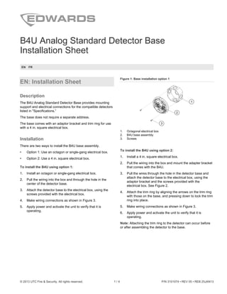
  • 1. © 2013 UTC Fire & Security. All rights reserved. 1 / 4 P/N 3101074 • REV 05 • REB 25JAN13 B4U Analog Standard Detector Base Installation Sheet EN FR EN: Installation Sheet Description The B4U Analog Standard Detector Base provides mounting support and electrical connections for the compatible detectors listed in "Specifications.” The base does not require a separate address. The base comes with an adaptor bracket and trim ring for use with a 4 in. square electrical box. Installation There are two ways to install the B4U base assembly. • Option 1: Use an octagon or single-gang electrical box. • Option 2: Use a 4 in. square electrical box. To install the B4U using option 1: 1. Install an octagon or single-gang electrical box. 2. Pull the wiring into the box and through the hole in the center of the detector base. 3. Attach the detector base to the electrical box, using the screws provided with the electrical box. 4. Make wiring connections as shown in Figure 3. 5. Apply power and activate the unit to verify that it is operating. Figure 1: Base installation option 1 2 3 1 1. Octagonal electrical box 2. B4U base assembly 3. Screws To install the B4U using option 2: 1. Install a 4 in. square electrical box. 2. Pull the wiring into the box and mount the adapter bracket that comes with the B4U. 3. Pull the wires through the hole in the detector base and attach the detector base to the electrical box, using the adaptor bracket and the screws provided with the electrical box. See Figure 2. 4. Attach the trim ring by aligning the arrows on the trim ring with those on the base, and pressing down to lock the trim ring into place. 5. Make wiring connections as shown in Figure 3. 6. Apply power and activate the unit to verify that it is operating. Note: Attaching the trim ring to the detector can occur before or after assembling the detector to the base.
  • 2. 2 / 4 P/N 3101074 • REV 05 • REB 25JAN13 Figure 2: Base installation option 2 1 3 4 5 2 6 2 1. 4 in. square electrical box 2. Adaptor bracket 3. B4U base assembly 4 Screws 5. Trim ring 6. Aligning arrows Wiring Wire in accordance with NFPA 72 or CAN/ULC-S524. Be sure to observe the polarity of the terminals on the terminal block as shown in the diagram. Break the wire run at each terminal. Do not loop signaling circuit field wires around terminals. Caution: To avoid accidental damage to the panel, disconnect all power before wiring the unit. Note: If shielded cable is used, the following recommendations apply: • Shielded wire is required only in environments with very high electrical noise. • Use of shield connections must be continuous and must be insulated from ground. Electrical tape is recommended as a minimum to insulate the shield. • For Class B wiring, all shields must be continuous and insulated from ground, except at the originating panel. Figure 3: Base wiring (option 2 installation shown) 1 3 2 4 5 6 1 2 5 1. From previous device or controller 2. Optional trim ring 3. Optional bracket 4. Maximum resistance per wire must not exceed 10 Ω 5. To next device Terminal Description Terminal Description 1 SLC in + and SLC out (+) 4 Not used 2 SLC in − 5 Remote LED + 3 Not used 6 Remote LED − and SLC out − Specifications Base diameter Without trim ring With trim ring 4.35 in. (110.49 mm) 6.0 in. (152 mm) Height from box (including detector) 2.08 in. (53 mm) Maximum distance Ceiling Wall Not less than 4 in. (100 mm) from the sidewall Between 4 and 12 in. (100 and 300 mm) from the ceiling Wire size 12 to 18 AWG wire (0.75 to 2.5 mm²) Compatible detectors FX-PD, E-PD, FX-PHD, E-PHD, FX-HD, E-HD, V-PS, V-PHS, V-HRD, and V-HFD Compatible electrical boxes 4 × 4 in. octagonal ring (mud box) 1-7/8 in. (47 mm) deep single-gang box 4 in. square x 2-1/2 in. (64 mm) deep box (requires using the included adaptor bracket and trim ring) Operating environment Temperature Relative humidity 32 to 120°F (0 to 49°C) 0 to 93% noncondensing Storage temperature range −4 to 140°F (−20 to 60°C)
  • 3. P/N 3101074 • REV 05 • REB 25JAN13 3 / 4 Regulatory information Manufacturer Edwards, A Division of UTC Fire & Security Americas Corporation, Inc. 8985 Town Center Parkway, Bradenton, FL 34202, USA Year of manufacture The first two digits of the date code (located on the product identification label) are the year of manufacture North American standards FCC Part 15, Subpart J, Class B; DOC, Class/MDC Class B. UL 268, UL 521, CAN/ULC-S529-09, CAN/ULC-S530-M91 Contact information For contact information, see our Web site: www.edwardsutcfs.com. FR : Fiche D'Installation Description La base analogique standard B4U pour détecteur fonctionne avec les détecteurs compatibles répertoriés à la section « Fiche technique ». La base n'exige pas une adresse séparée. La base vient avec une parenthèse d'adapteur et un anneau d'équilibre pour l'usage avec les 4 po. boîte électrique carrée. Installation Il y a deux manières d'installer le montage bas de B4U. • Option 1 : Utilisez une boîte électrique d'octogone ou de simple-troupe. • Option 2 : Utilisez une boîte électrique qui est 4 po. carré. Pour installer le B4U utilisant l'option 1 : 1. Installez une boîte électrique d'octogone ou de simple- troupe. 2. Tirez le câblage dans la boîte et par le trou au centre de la base de détecteur. 3. Attachez la base de détecteur dans la boîte électrique, utilisant les vis fournies par la boîte électrique. 4. Établissez les rapports de câblage suivant les indications du Figure 3. 5. Activez la base pour vérifier qu'elle fonctionne. Figure 1 : Option 1 d’installation de la base 2 3 1 1. Boîte électrique octogonale 2. La base de B4U 3. Vis Pour installer le B4U utilisant l'option 2 : 1. Installez une boîte électrique qui est 4 po. carré. 2. Tirez le câblage dans la boîte et par la parenthèse d'adapteur qui vient avec le B4U. 3. Attachez la base de détecteur dans la boîte électrique, utilisant la parenthèse d'adapteur et les vis fournies par la boîte électrique. Voir la Figure 2. 4. Alignez les marques sur l’anneau de garniture avec celles de la plaque de la base, pressez l’anneau dans la plaque et faites pivoter l’anneau jusqu’à ce qu’elle se verrouille en place. 5. Établissez les rapports de câblage suivant les indications du Figure 3. 6. Activez la base pour vérifier qu'elle fonctionne. Figure 2 : Option 2 d’installation de la base 1 3 4 5 2 6 2 1. Flèches de alignement 2. Parenthèse facultative 3. Boîte carrée de 10 cm (4 po) 4. La base de B4U 5. Vis 6. Anneau facultatif d'équilibre
  • 4. 4 / 4 P/N 3101074 • REV 05 • REB 25JAN13 Remarque : La fixation de l'anneau d'équilibre au détecteur peut se produire avant ou après assembler le détecteur à la base. Filage Câblez conformément aux normes NFPA 72 et CAN/ULC-S524. Assurez-vous de bien observer la polarité des bornes sur le bornier, tel qu’indiqué sur le diagramme. Interrompez le filage à chacune des bornes. Ne faites pas de boucle autour des bornes avec les câbles du champ du circuit de signalisation. Avertissement : Pour éviter tout dommage accidentel au panneau, débranchez toute alimentation électrique avant de câbler le dispositif. Remarque : Recommandations à suivre si vous utilisez un câble armé : • Un fil blindé est requis UNIQUEMENT dans les environnements à interférences électriques élevées. • Le blindage doit être continu et isolé de la terre. La bande électrique est recommandée comme minimum pour isoler le bouclier. • Pour le câblage de la classe B, tous les boucliers doivent être continus et isolés de la terre, à moins qu'au panneau d'origine. Figure 3 : Câblage de la base 1 3 2 4 5 6 1 2 5 1. Du dispositif ou du contrôleur précédent 2. La résistance maximum par fil ne doit pas dépasser 10 Ω 3. Au prochain dispositif 4. Parenthèse facultative 5. Anneau facultatif d'équilibre Borne Description Borne Description 1 Entrée SLC + et sortie SLC + 4 Non utilisé 2 Entrée SLC − 5 DEL à distance + 3 Non utilisé 6 DEL à distance − et sortie SLC − Fiche technique Diamètre de la base sans la plaque de base avec la plaque de la base 110.49 mm (4.35 po.) 152 mm (6 po.) Hauteur à partir du coffret (détecteur inclus) 53 mm (2.08 po.) Distance maximale montage du plafond montage mural Pas moins que 100 mm (4 po.) du mur lateral Entre 100 et 300 mm (4 et 12 po.) du plafond Dimensions du câble Câbles de 12 à 18 AWG (0.75 à 2.5 mm2 ) Détecteurs compatibles FX-PD, E-PD, FX-PHD, E-PHD, FX-HD, E-HD, V-PS, V-PHS, V-HRD et V-HFD Coffrets électriques compatibles Anneau octogonal de 10 x 10 cm (4 x 4 po.) (boîte à boue) Coffret de 47 mm de profond Coffret carrée de 10 cm (4 po.) x 64 mm (2.5 po.) de profond (exige utilisant la parenthèse d'adapteur et l'anneau d'équilibre qui sont inclus) Cadre opérationnel Température Plage d’humidité relative 0 à 4°C (32 à 12°F) 0 à 93 sans condensation Plage de la température d’entreposage −20 à 60°C (−4 à 140°F) Référencement des agences Fabricant Edwards, A Division of UTC Fire & Security Americas Corporation, Inc. 8985 Town Center Parkway, Bradenton, FL 34202, USA L’année de fabrication Les deux premiers chiffres du code de date (situé sur l'étiquette d'identification de produit) sont l'année de la fabrication Normes nord- américaines FCC Part 15, Subpart J, Class B, DOC Class/MDC Class B. UL 268, UL 521, CAN/ULC-S529-09, CAN/ULC-S530-M91 Coordonnées Pour obtenir nos coordonnées, consultez le site Web www.edwardsutcfs.com.