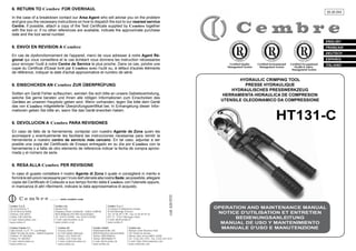
Cembre HT131-C Hydraulic Crimping Tool (up to 400sqmm) Manual
•
0 j'aime•1,300 vues

Cembre HT131-C Hydraulic Crimping Tool (up to 400sqmm) Manual

Recommandé
Recommandé
Contenu connexe
Tendances
Tendances (11)
Similaire à Cembre HT131-C Hydraulic Crimping Tool (up to 400sqmm) Manual
Similaire à Cembre HT131-C Hydraulic Crimping Tool (up to 400sqmm) Manual (20)
Plus de Thorne & Derrick International
Plus de Thorne & Derrick International (20)
Cembre HT131-C Hydraulic Crimping Tool (up to 400sqmm) Manual
- 1. 6. RETURN TO Cembre FOR OVERHAUL 05 M 094 In the case of a breakdown contact our Area Agent who will advise you on the problem and give you the necessary instructions on how to dispatch the tool to our nearest service Centre; if possible, attach a copy of the Test Certificate supplied by Cembre together with the tool or, if no other references are available, indicate the approximate purchase date and the tool serial number. ENGLISH 6. ENVOI EN REVISION A Cembre FRANÇAIS DEUTSCH En cas de dysfonctionnement de l'appareil, merci de vous adresser à notre Agent Régional qui vous conseillera et le cas échéant vous donnera les instruction nécessaires pour envoyer l'outil à notre Centre de Service le plus proche. Dans ce cas, joindre une copie du Certificat d'Essai livré par Cembre avec l'outil ou, à défaut d'autres éléments de référence, indiquer la date d'achat approximative et numéro de série. ESPAÑOL Certified Quality Management System Certified Environmental Management System Certified Occupational Health & Safety Management System ITALIANO HYDRAULIC CRIMPING TOOL PRESSE HYDRAULIQUE HYDRAULISCHES PRESSWERKZEUG HERRAMIENTA HIDRAULICA DE COMPRESION UTENSILE OLEODINAMICO DA COMPRESSIONE 6. EINSCHICKEN AN Cembre ZUR ÜBERPRÜFUNG Sollten am Gerät Fehler auftauchen, wenden Sie sich bitte an unsere Gebietsvertretung, welche Sie gerne beraten und Ihnen alle nötigen Informationen zum Einschicken des Gerätes an unseren Hauptsitz geben wird. Wenn vorhanden, legen Sie bitte dem Gerät das von Cembre mitgelieferte Überprüfungszertifikat bei; In Ermangelung dieser Informationen geben Sie bitte an, wann Sie das Gerät erworben haben. HT131-C 6. DEVOLUCION A Cembre PARA REVISIONES En caso de fallo de la herramienta, contactar con nuestro Agente de Zona quien les aconsejará y eventualmente les facilitará las instrucciones necesarias para remitir la herramienta a nuestro centro de servicio más cercano. En tal caso, adjuntar a ser posible una copia del Certificado de Ensayo entregado en su día por Cembre con la herramienta o a falta de otro elemento de referencia indicar la fecha de compra aproximada y el número de serie. 6. RESA ALLA Cembre PER REVISIONE www.cembre.com Cembre S.p.A. Via Serenissima, 9 25135 Brescia (Italia) Telefono: 030 36921 Telefax: 030 3365766 E-mail: info@cembre.com www.cembre.it Cembre España S.L. Calle Verano, 6 y 8 - P.I. Las Monjas 28850 Torrejón de Ardoz - Madrid (España) Teléfono: 91 4852580 Telefax: 91 4852581 E-mail: info@cembre.es www.cembre.es Cembre Ltd. Dunton Park Kingsbury Road, Curdworth - Sutton Coldfield West Midlands B76 9EB (Great Britain) Tel.: 01675 470440 - Fax: 01675 470220 E-mail: sales@cembre.co.uk www.cembre.co.uk Cembre AS Fossnes Senter N-3160 Stokke (Norway) Phone: (47) 33361765 Telefax: (47) 33361766 E-mail: cembre@cembre.no www.cembre.no Cembre S.a.r.l. 22 Avenue Ferdinand de Lesseps 91420 Morangis (France) Tél.: 01 60 49 11 90 - Fax: 01 60 49 29 10 B.P. 37 - 91421 Morangis Cédex E-mail: info@cembre.fr www.cembre.fr Cembre GmbH Heidemannstraße 166 80939 München (Deutschland) Telefon: 089/3580676 Telefax: 089/35806777 E-mail: info@cembre.de www.cembre.de cod. 6261010 In caso di guasto contattare il nostro Agente di Zona il quale vi consiglierà in merito e fornirà le istruzioni necessarie per l’invio dell'utensile alla nostra Sede; se possibile, allegare copia del Certificato di Collaudo a suo tempo fornito dalla Cembre con l'utensile oppure, in mancanza di altri riferimenti, indicare la data approssimativa di acquisto. Cembre Inc. Raritan Center Business Park 181 Fieldcrest Avenue Edison, New Jersey 08837 (USA) Tel.: (732) 225-7415 - Fax: (732) 225-7414 E-mail: Sales.US@cembreinc.com www.cembreinc.com OPERATION AND MAINTENANCE MANUAL NOTICE D'UTILISATION ET ENTRETIEN BEDIENUNGSANLEITUNG MANUAL DE USO Y MANTENIMIENTO MANUALE D'USO E MANUTENZIONE
- 2. ! ▲ 35 WARNING LABELS - ETIQUETTES SIGNALETIQUES - WARNSCHILDER ETIQUETAS DE ATENCION - ETICHETTE D'AVVERTENZA 37 36 34 38 33 39 32 40 31 30 TG 0356 29 1 1 – – – – – 2 27 26 79 80 3 4 When operating the tool keep hands away from the danger zone. Au cours du sertissage, tenir les mains éloignées de la zone de danger. Während des Verpressens nicht mit den Händen in den Pressbereich langen. Durante su utilización, mantenga las manos fuera de la zona de peligro. Durante l'utilizzo, mantenere le mani fuori dalla zona di pericolo. – – – – – Do not operate when dies are not in place. Insérer les matrices avant d’actionner l’outil. Nicht ohne Presseinsatzpaar betätigen. No poner en presión sin matrices. Non mandare in pressione l’utensile senza le matrici inserite. 71 82 68 12 11 67 10 09 66 08 65 60 64 59 63 TYPE FORCE - HT131-C 130 kN Made in Italy 2 Tool type Outil type Handwerkzeug Typ Herramienta tipo Tipo di utensile - Force Force Kraft Fuerza Forza Year Année Jahr Año Anno 06 04 3 - 07 05 62 1 58 61 03 1 2 02 3 01 This manual is the property of Cembre: any reproduction is forbidden without written permission. Ce manuel est la proprieté de Cembre: toute reproduction est interdite sauf autorisation écrite. Der Firma Cembre bleibt das Eigentumsrecht der Bedienungsanleitung vorbehalten. Ohne vorherige schriftliche Genehmigung darf die Bedienungsanleitung weder vollständig noch teilweise vervielfältigt werden. Este manual es propiedad de Cembre. Toda reproducción está prohibida sin autorización escrita. Questo manuale è di proprietà della Cembre. Ogni riproduzione é vietata se non autorizzata per scritto. 1 FIG. 5 30 45 46 47 48 49 51 13 84 69 E 53 14 83 70 43 44 18 17 16 15 81 72 2 41 42 22 21 20 19 73 74 75 76 77 78 Before using the tool, carefully read the instructions in this manual. Avant d'utiliser cet outil, lire attentivement les instructions de cette notice. Vor Inbetriebnahme unbedingt die Bedienungsanleitung durchlesen. Antes de utilizar la herramienta, leer atentamente las instrucciones contenidas en este manual. Prima di utilizzare l'utensile, leggere attentamente le istruzioni contenute in questo manuale. – – – – – E 25 24 23 4 3 E-E 28 LONGITUDINAL SECTION COUPE LONGITUDINALE SCHNITTZEICHNUNG SECCION LONGITUDINAL SEZIONE LONGITUDINALE 54 55 56 57 Serial number Numéro de série Seriennummer Número de serie Numero di matricola
- 3. ENGLISH HYDRAULIC CRIMPING TOOL HT131-C 1. GENERAL CHARACTERISTICS 01 – Application range: suitable for compression of electrical connectors on conductors up to ............................................................. 400 mm2 (800 MCM) – Crimping force: ...................................................................... 130 kN – Rated operating pressure: .................................................... 700 bar (12.3 lbs) – Recommended oil: ............................... AGIP ARNICA 22 ESSO INVAROL EP22 56 (18.6 in.) (5.7 in.) (13.5 in.) – Weight (without dies): .............................................................. 5,5 kg 03 (10,000 psi) – Dimensions: length ................................................................ 473 mm width with handles closed ................................. 144 mm width with handles open ..................................... 344 mm 04 (14.6 sh ton) or or equivalent – Operating positions. The three operating positions are identified on the main handle, which rotates relative to the reference symbol, (see Fig. 1). 65 LOCK Rest position (Handles locked): lock handles togethe when tool is not in use. 73 Release position: close the moveable handle (56) against the main handle (04), in order to discharge the oil pressure and retract the dies. Operating position: operate the moveable handle (56), to build up pressure and close the dies. – Advancing speed. The tool has a twin speed operation and automatically switches from a rapid advancing speed of the ram to a slower, more powerful crimping speed. – Safety. The tool is provided with a max pressure valve; MPC1 special manometer, is available as an optional accessory to check the proper setting of the valve. FIG. 4 TOOL POSITION FOR MAINTENANCE OPERATIONS POSITION DE L'OUTIL POUR L'ENTRETIEN WERKZEUG WARTUNGSPOSITION COLOCACION PARA LAS OPERACIONES DE MANTENIMIENTO POSIZIONAMENTO PER LE OPERAZIONI DI MANUTENZIONE 29 2
- 4. ENGLISH 2. INSTRUCTIONS FOR USE (Ref. to Fig. 1 and 2) 2.1) Setting LOCK With the tool is in rest position operate as follows: – Select the appropriate die set for the connector. – Insert the die (91) in the upper seat of the tool head until it is locked by die/head pin (34). To ease the die insertion, keep die/head release pin (32) depressed. – Insert the die (90) in the seat on the head of main ram (28) until it is locked by die/ram retainer pin (39). To ease this operation, keep die/ram release pin (38) depressed. – Insert the conductor in the connector. – Position the connector between the dies and ensure the correct location of the crimp. 32 2.2) Die advancement Never place the tool under pressure without inserting the dies, as this could cause damage to the head and the ram. 34 Make sure the dies are exactly positioned on desired crimp point, otherwise re-open dies following instructions as per § 2.4 and position the connector again. 2.3) Crimping – Continue operating the moveable handle (56). The tool will automatically change over to the high pressure stage. The ram will advance until the dies meet. – It is recommended to continue pumping until the maximum pressure valve is activated and a "click" is heard. 2.4) Dies re-opening – Rotate the main handle to release position . Close handles thoroughly: the ram will then retract, with the consequent opening of the dies. 2.5) Rest setting ; the LOCK – Retract thoroughly the ram, operating as per § 2.4. – Keeping handles closed rotate further the main handle to rest position moveable handle will be thus locked. – Store the tool in the case. 3 FIG. 3 STORAGE CASE RANGEMENT LAGERUNG ALMACENAMIENTO CUSTODIA 28 28 31 91 90 39 mm .) ÷ 4 6 in ~ 3 - 0.1 11 (0. – Set the tool on release position by rotating main hanle (04); open the moveable handle (56). – Rotate main handle (04) to operating position . – Operate moveable handle (56) for lower die advancement. This first stage rapidly closes the dies to the connector. ! ▲ FIG. 2 DIE REPLACEMENT INSERTION DES MATRICES EINRASTEN PRESSEINSÄTZE INSERCION DE LAS MATRICES INSERIMENTO MATRICI 38
- 5. ENGLISH 2.6) Die replacement (Ref. to Fig. 2) 32 - Reference symbol - Repère fixe - Referenzsymbol - Simbolo de referencia - Simbolo di riferimento 39 To replace dies operate as follows: – Upper die (91) Take the die off its guide by pushing the die/head release pin (32). Insert replacement die until secured by the die retaining pin (34). 34 28 – Lower die (90) Take the die off its guide by pushing the die/ram release pin (38). To facilitate this operation an advancement of 3÷4 mm (0.11-0.16 in.) of the ram (28) is suggested. Insert the new die in its guide till die/ram retainer pin (39) will hold it properly. 13 38 3. WARNING 73 The tool is robust and requires very little daily maintenance. Compliance with the following points, should help to maintain the optimum performance of the tool. 3.1) Accurate cleaning LOCK 54 56 04 - Rest position - Release position - Repère de repos 3.2) Storage (Ref. to Fig. 3) When not in use, the tool should be stored and transported in the plastic case, to prevent damage. These plastic case (Type VAL P3) is dimensioned 620x380xh135 mm (24.4x14.9x5.3 in.) and weights 2,5 kg (5.5 lbs). - Repère de - Repère de décompression travail - Operating position - Ruhestellungs- - Druckablassposition position - Arbeitsposition - Posición de reposo - Posición de liberación - Posición de trabajo - Posizione di riposo - Posizione di rilascio Dust, sand and dirt are a danger for any hydraulic device. Every day, after use, the tool must be wiped with a clean cloth, taking care to remove any residue, especially close to pivots and moveable parts. - Posizione di lavoro 3.3) Head rotation For ease of operation, the tool head can rotate through 180°. Warning: do not attempt to turn the head if the hydraulic circuit is pressurised. FIG. 1 OVERALL VIEW VUE D'ENSEMBLE GESAMTANSICHT VISTA DEL CONJUNTO VISTA D'ASSIEME 27 4
- 6. ENGLISH ITALIANO 5. LISTA DEI COMPONENTI (Rif. a Fig. 5) Air in the hydraulic circuit may affect the performance of the tool; e.g. no lower die advancement, slow advancement of the lower die; lower die pulsating. In this case proceed as follows: 4.1) To purge air bubbles from hydraulic circuit a – Hold tool upright in a vice with handles open (Fig. 4). b – By an hexagonal 2,5 mm key, remove screw (65) and main handle (04) to expose oil reservoir (03). c – Remove reservoir cap (01). d – Operate three or four times the moveable handle (56), to advance the ram (28). e – Depress pressure release pin (73) until ram is fully retracted. f – Repeat points (d - e) at least five times, to ensure all air bubbles in the hydraulic circuit are purged into the reservoir. g – If the oil level is low, top up as directed in § 4.2. h – Remove all air from reservoir and fit cap (01). i – Assemble main handle (04), and holding screw (65). If the tool continues to malfunction return the tool for service/repair as detailed in § 6. 4.2) Oil top up Every six months check the oil level in the reservoir. If necessary, top up the oil level to the upper lip of the reservoir and remove all air from the reservoir, see 4.1, points a, b, c, e, g, h and i. Always use clean recommended oil, see § 1. Do not use old or recycled oil. Do not use hydraulic brake fluid. ! ▲ Ensure that disposal of used oil is in accordance with current legislation. N° Codice Part. DENOMINAZIONE 6800040 01 TAPPO SERBATOIO 6380265 ● 02 IMPUGNATURA MANICO FISSO 6720100 03 SERBATOIO 6480043 ● 04 MANICO FISSO 6760014 ● 05 SPINA ELASTICA 3x4 6780105 ● 06 SUPPORTO MANICO FISSO 6360260 ★ 07 GUARNIZIONE OR 6040685 08 ANELLO GUIDA 6900621 09 VITE ASPIRAZIONE COMPL. 6360160 ★ 10 GUARNIZIONE OR 6740060 ★ 11 SFERA 3/16" 6520765 ★ 12 MOLLA ASPIRAZIONE 6160234 13 CORPO 6740060 ★ 14 SFERA 3/16" 6520765 ★ 15 MOLLA ASPIRAZIONE 6740140 ★ 16 SFERA 9/32" 6520180 ★ 17 MOLLA ANTIRITORNO 6340566 18 GRANO TENUTA SFERA 6900059 19 VITE M 4x8 6100020 20 CHIAVETTA 6700250 ▲ 21 ANELLO ELASTICO D 36 6170140 ▲ 22 COPERCHIO MOLLA 6360420 ★ ▲ 23 GUARNIZIONE OR 6040320 ★ ▲ 24 ANELLO BK 6520620 ▲ 25 MOLLA ESTERNA RICH. PISTONE 6520610 ▲ 26 MOLLA INTERNA RICH. PISTONE 6300040 ▲ 27 FUNGO 6620315 ▲ 28 PISTONE 6900211 29 VITE 5x10 6100035 30 CHIAVETTA 6370212 ■ 31 GANCIO "C" 6620460 ■ 32 PIST. SBLOCCO MATR./TESTA 6760160 ■ 33 SPINA ELASTICA D 3x28 6620440 ■ 34 PIST. FERMA MATR./TESTA 6522006 ■ 35 MOLLA PISTONCINO 6340540 ■ 36 GRANO M 10x8 6760040 ▲ 37 SPINA ELASTICA D 3x8 6620445 ▲ 38 PIST. SBLOCCA MATR./PIST. 6620320 ▲ 39 PIST.FERMA MATR./PISTONE 6522006 ▲ 40 MOLLA PISTONCINO 6362035 ★ 41 GUARNIZIONE PIENA 6362010 ★ 42 GUARNIZIONE 6641140 ★ 43 ANELLO BK 6360240 ★ 44 GUARNIZIONE OR Q.tà N° Codice Part. DENOMINAZIONE Q.tà 1 1 1 1 1 1 1 2 1 1 1 1 1 1 1 1 1 1 1 1 1 1 1 1 1 1 1 1 1 1 1 1 1 1 1 1 1 1 1 1 1 1 1 1 6362020 6620382 6760320 6780265 6700100 6080060 6560420 6200030 6760280 6480269 6380240 6232006 6650118 6232062 6760040 6740020 6520280 6640205 6900060 6895050 6360160 6740120 6600100 6520260 6740080 6340540 6620120 6360120 6040060 6080080 6900280 6180200 6340566 6520180 6740140 6635011 6520861 6340720 6480042 6620316 6370213 6480194 6000074 ★ 45 46 ✚ 47 ✚ 48 ★ 49 ✚ 51 53 ✚ 54 ✚ 55 ✚ 56 ✚ 57 58 59 60 ▲ 61 ★ 62 63 64 65 66 ★ 67 ★ 68 69 70 ★ 71 72 73 ★ 74 ★ 75 76 ✚ 77 ✚ 78 79 ★ 80 ★ 81 82 83 84 ● ▲ ■ ✚ ★ GUARNIZIONE PISTONE POMPANTE SPINA ELASTICA D 5x30 SUPPORTO MANICO MOBILE ANELLO ELASTICO BUSSOLA MANICO MOBILE PERNO MANICO MOBILE DENTE ARRESTO MANICO MOBILE SPINA ELASTICA D 4x30 MANICO MOBILE IMPUGNAT. MANICO MOBILE ETICHETTA RIVETTO ø 2,5X3,5 TARGHETTA (TG. 0262) SPINA ELASTICA D 3x8 SFERA 1/4" MOLLA ROSETTA ZIGRINATA VITE 4x8 VALVOLA COMPLETA GUARNIZIONE OR SFERA 7/32" NOTTOLINO SPINGI SFERA MOLLA SCARICO SFERA 5/16" GRANO M 10x8 PIST. SBLOCCO PRESSIONE GUARNIZIONE OR ANELLO BK BUSSOLA PIST. RITORNO PRESS. VITE 5x18 DADO M5 GRANO TENUTA SFERA MOLLA ANTIRITORNO SFERA 9/32" PUNTALE SCARICO PRESS. MOLLA SBLOCCO PRESSIONE GRANO SCARICO PRESSIONE MANICO FISSO MONTATO PISTONE MONTATO GANCIO “C” MONTATO MANICO MOBILE MONTATO CONFEZIONE RICAMBIO 1 1 1 1 4 4 2 1 1 1 1 1 2 1 1 1 1 1 1 1 1 1 1 1 1 1 1 1 1 1 1 1 1 1 1 1 1 1 I particolari indicati con (★) sono quelli che la Cembre consiglia di cambiare sempre nel caso di un eventuale smontaggio dell'utensile. Detti particolari sono fornibili su richiesta nella “Confezione Ricambio per HT131-C “. 5 26 La garanzia decade qualora vengano utilizzate parti di ricambio non originali Cembre. 4. MAINTENANCE (Ref. to Fig. 4 and 5) Per ordinare parti di ricambio, specificare sempre i seguenti punti: - numero di codice del componente - denominazione del componente - tipo dell'utensile - numero di matricola dell'utensile
- 7. ITALIANO ENGLISH 4. MANUTENZIONE (Rif. a Fig. 4 e 5) 5. PARTS LIST (Ref. to Fig. 5) 4.1) Per espellere le bolle d’aria a – Capovolgere l'utensile e bloccarlo in una morsa in posizione verticale (ved. Fig. 4) con il manico mobile (56) divaricato. b – Svitare la vite (65) con una chiave esagonale da 2,5 mm, e sfilare completamente il manico fisso (04), mettendo in vista il serbatoio in gomma (03) dell’olio. c – Estrarre il tappo (01) del serbatoio dell’olio. d – Azionare tre o quattro volte il manico mobile, facendo avanzare il pistone (28). e – Rilasciare la pressione dell’olio comprimendo, con un cacciavite od altro attrezzo simile, il pistoncino di sblocco pressione (73) fino a che il pistone non sia arretrato completamente ed in modo che l’olio sia ritornato tutto nel serbatoio. f – Ripetere le operazioni (d - e) almeno 5 volte in modo che le bolle d’aria, eventualmente presenti nel circuito oleodinamico, vengano espulse e si raccolgano nel serbatoio dell’olio. g – Prima di richiudere il serbatoio si deve eliminare completamente l’aria. Se il livello dell’olio fosse basso, effettuare un rabbocco come indicato al punto 4.2. h – Inserire il tappo. i – Rimontare il manico fisso, inserire la vite (65) nella sua sede e bloccarla. Nel caso eccezionale che l’utensile, anche dopo queste operazioni di manutenzione, non funzionasse correttamente (il pistone non avanza o pulsa) é consigliabile rimandarlo al più vicino Agente Cembre per la sua completa revisione (vedi § 6.). 4.2) Rabbocco dell'olio Il serbatoio dell'olio deve essere sempre pieno; ciò eviterà che si formino bolle d'aria al suo interno. Consigliamo di verificare il livello dell'olio almeno ogni 6 mesi; se il livello fosse basso, procedere al rabbocco eseguendo le operazioni descritte precedentemente in a, b, c ed e, quindi riempire raso il serbatoio. Completare con le operazioni h ed i. Usare esclusivamente un tipo d’olio consigliato al § 1. Mai usare olio rigenerato o usato. E' necessario che l'olio sia pulito. ! ▲ In occasione di eventuali sostituzioni dell'olio, smaltire l'olio esausto attenendosi scrupolosamente alla legislazione specifica in materia. 25 Code N° Item DESCRIPTION 6800040 01 RESERVOIR CAP 6380265 ● 02 MAIN HANDLE GRIP 6720100 03 OIL RESERVOIR 6480043 ● 04 MAIN HANDLE 6760014 ● 05 3x4 PIN 6780105 ● 06 MAIN HANDLE SUPPORT 6360260 ★ 07 O-RING 6040685 08 GUIDING RING 6900621 09 SUCTION SCREW 6360160 ★ 10 O-RING 6740060 ★ 11 3/16" BALL 6520765 ★ 12 SUCTION SPRING 6160234 13 BODY 6740060 ★ 14 3/16" BALL 6520765 ★ 15 SUCTION SPRING 6740140 ★ 16 9/32" BALL 6520180 ★ 17 SPRING 6340566 18 BALL POSITIONING DOWEL 6900059 19 4x8 SCREW 6100020 20 KEY 6700250 ▲ 21 SPRING RING 6170140 ▲ 22 SPRING COVER 6360420 ★ ▲ 23 O-RING 6040320 ★ ▲ 24 BACK-UP RING 6520620 ▲ 25 RAM RETURN OUTER SPRING 6520610 ▲ 26 RAM RETURN INNER SPRING 6300040 ▲ 27 RAM SPRING GUIDE 6620315 ▲ 28 RAM 6900211 29 5x10 SCREW 6100035 30 KEY 6370212 ■ 31 "C" HEAD 6620460 ■ 32 DIE HEAD RELEASE PIN 6760160 ■ 33 3x28 SPLIT PIN 6620440 ■ 34 DIE HEAD RETAINER PIN 6522006 ■ 35 SPRING 6340540 ■ 36 10x8 GRUB SCREW 6760040 ▲ 37 3x8 SPLIT PIN 6620445 ▲ 38 DIE RAM RELEASE PIN 6620320 ▲ 39 DIE RAM RETAINER PIN 6522006 ▲ 40 SPRING 6362035 ★ 41 SEAL 6362010 ★ 42 SEAL 6641140 ★ 43 BACK-UP RING 6360240 ★ 44 O-RING Qty Code N° Item DESCRIPTION Qty 1 1 1 1 1 1 1 2 1 1 1 1 1 1 1 1 1 1 1 1 1 1 1 1 1 1 1 1 1 1 1 1 1 1 1 1 1 1 1 1 1 1 1 1 6362020 6620382 6760320 6780265 6700100 6080060 6560420 6200030 6760280 6480269 6380240 6232006 6650118 6232062 6760040 6740020 6520280 6640205 6900060 6895050 6360160 6740120 6600100 6520260 6740080 6340540 6620120 6360120 6040060 6080080 6900280 6180200 6340566 6520180 6740140 6635011 6520861 6340720 6480042 6620316 6370213 6480194 6000074 ★ 45 46 ✚ 47 ✚ 48 ★ 49 ✚ 51 53 ✚ 54 ✚ 55 ✚ 56 ✚ 57 58 59 60 ▲ 61 ★ 62 63 64 65 66 ★ 67 ★ 68 69 70 ★ 71 72 73 ★ 74 ★ 75 76 ✚ 77 ✚ 78 79 ★ 80 ★ 81 82 83 84 ● ▲ ■ ✚ ★ SEAL PUMPING RAM 5x30 SPLIT PIN MOVEABLE HANDLE SUPPORT SPRING RING MOVEABLE HANDLE BUSHING MOVEABLE HANDLE PIVOT MOVEABLE HANDLE LATCH 4x30 SPLIT PIN MOVEABLE HANDLE MOVEABLE HANDLE GRIP LABEL RIVET METAL LABEL (TG. 0262) 3x8 SPLIT PIN 1/4" BALL MAIN HANDLE SPRING WASHER 4x8 SCREW MAX PRESSURE VALVE O-RING 7/32" BALL BALL POSITIONING DOWEL SPRING 5/16" BALL 10x8 GRUB SCREW PRESSURE RELEASE PIN O-RING BACK-UP RING PRESSURE RELEASE RAM BUSHING 5x18 SCREW M5 NUT BALL POSITIONING DOWEL NO RETURN SPRING 9/32" BALL PRESSURE RELEASE PIN PRESSURE RELEASE SPRING PRESSURE RELEASE DOWEL COMPLETE MAIN HANDLE COMPLETE RAM COMPLETE “C” HEAD COMPLETE MOVEABLE HANDLE SPARE PARTS PACKAGE 1 1 1 1 4 4 2 1 1 1 1 1 2 1 1 1 1 1 1 1 1 1 1 1 1 1 1 1 1 1 1 1 1 1 1 1 1 1 The items marked (★) are those Cembre recommend replacing if the tool is disassembled. These items are included on request in the “HT131-C Spare Parts Package” 6 The guarantee is void if parts used are not Cembre original spares. Bolle d'aria dell'olio possono causare un funzionamento non corretto dell'utensile. Tale situazione si manifesta con un comportamento anomalo dell’utensile: pompando, il pistone non avanza oppure si muove molto lentamente oppure pulsa. In questo caso bisogna agire nel modo seguente: When ordering spare parts always specify the following: - code number of item - name of item - type of tool - tool serial number
- 8. FRANÇAIS ITALIANO 2.6) Cambio delle matrici (Rif. a Fig. 2) PRESSE HYDRAULIQUE TYPE HT131-C 1. CARACTERISTIQUES GENERALES – Domaine d'application: conçue pour le sertissage des connecteurs électriques pour câbles jusqu'à ................................. 400 mm2 (800 MCM) – Force de sertissage: .............................................................. 130 kN (14.6 sh ton) – Pression nominale: ................................................................ 700 bar (10,000 psi) – Dimensions: hauteur .............................................................. 473 mm largeur (bras mobile fermé) ............................... 144 mm largeur (bras mobile ouvert) .............................. 344 mm (18.6 in.) (5.7 in.) (13.5 in.) – Poids (sans matrices): ............................................................ 5,5 kg ou ou équivalent – Matrice inferiore (90) Sfilare la matrice dalle sue guide tenendo premuto il pistoncino sblocca matrice/pistone (38) in modo da annullare l’azione di ritenuta del pistoncino ferma matrice/pistone (39). Si consiglia di far avanzare di 3÷4 mm (0.11 - 0.16 in.) il pistone (28) per facilitare l’operazione. Inserire la nuova matrice nelle guide sino al bloccaggio col pistoncino ferma matrice/pistone. (12.3 lbs) – Huile: ..................................................... AGIP ARNICA 22 ESSO INVAROL EP22 Per effettuare il cambio delle matrici operare come segue: – Matrice superiore (91) Sfilare la matrice dalle sue guide tenendo premuto il pistoncino sblocca matrice/testa (32)in modo da annullare l’azione di ritenuta del pistoncino ferma matrice/testa (34). Inserire la nuova matrice nelle guide fino al bloccaggio col pistoncino ferma matrice/testa. 3. AVVERTENZE L’utensile é robusto e non richiede attenzioni particolari; per ottenere un corretto funzionamento basterà osservare alcune semplici precauzioni: 3.1) Accurata pulizia – Positions de fonctionnement: les trois positions de fonctionnement de la presse sont mentionnées sur le bras principal (04), qui pivote sous le corps de presse, et sont sélectionnées face au repère fixe (voir Fig. 1). Tenere presente che la polvere, la sabbia e lo sporco rappresentano un pericolo per ogni apparecchiatura oleodinamica. Dopo ogni giorno d’uso si deve ripulire l’utensile con uno straccio pulito, avendo cura di eliminare lo sporco depositatosi su di esso, specialmente vicino alle parti mobili. 3.2) Custodia (Rif. a Fig. 3) Repère de décompression: l'outil à cette position, en amenant et maintenant le bras mobile (56) contre le bras principal (04) relache sa pression et ouvre ainsi les matrices. LOCK Repère de repos: c'est la position où l'outil doit être au repos. Le bras mobile (56) est bloqué. Per proteggere l'utensile da urti accidentali e dalla polvere, quando non viene utilizzato, é bene custodirlo nell'apposita valigetta in materiale plastico accuratamente chiusa. Detta valigetta (tipo VAL P3) ha dimensioni 620x380xh135 mm (24.4x14.9x5.3 in.) e pesa 2,5 kg (5.5 lbs). Repère de travail: l'outil à cette position, en actionnant le bras mobile (56), permet la montée en pression et la ferme ture des matrices. – Avance rapide: l'outil passe automatiquement de la vitesse rapide d'approche des matrices, à la vitesse lente de montée en pression. – Sécurité: l'outil est pourvu d'une valve de surpression. Pour vérifier le bon fonctionnement de cette valve, un manomètre spécial, notre réf. MPC1, est disponible à la demande. 7 3.3) Rotazione della testa La testa dell’utensile può ruotare di 180° rispetto al corpo, permettendo così all’operatore di eseguire il lavoro nella posizione più agevole. Attenzione: non forzare la testa tentando di ruotarla quando l’utensile é in pressione. 24
- 9. ITALIANO FRANÇAIS 2. ISTRUZIONI PER L’USO (Rif. a Fig. 1 e 2) 2. INSTRUCTIONS D'UTILISATION (Voir Fig. 1 et 2) 2.1) Preparazione 2.1) Mise en service 2.2) Accostamento delle matrici – Impugnare l’utensile e ruotare il manico fisso (04) in posizione di rilascio ; il manico mobile (56) si libera e può essere azionato. – Ruotare ulteriormente il manico fisso in posizione di lavoro . – Azionare il manico mobile; il pistone (28) avanzerà velocemente portando le matrici in contatto con il connettore. ! ▲ Mai mettere in pressione l’utensile senza le matrici inserite, ciò potrebbe causare il danneggiamento delle sedi della testa e del pistone. Assicurarsi che le matrici si trovino esattamente in corrispondenza con la zona da comprimere; in caso contrario riaprirle seguendo le istruzioni del punto 2.4 e riposizionare il connettore. 2.3) Compressione – Continuare ad azionare il manico mobile. Si passerà automaticamente dall’alta alla bassa velocità; il pistone avanzerà progressivamente fino a portare le matrici in battuta tra loro. – Consigliamo comunque di pompare fino all'intervento della valvola di massima pressione della quale si avvertirà lo scatto. Avec l'outil en position de repos procéder comme suit: – Prendre les matrices à utiliser selon le type de sertissage à effectuer. – Insérer la partie (91) de la matrice dans son guide supérieur dans la tete de l'outil jusqu'à son verrouillage par l'axe de verrouillage matrice/tete (34). – Insérer la partie (90) de la matrice dans sa guide dans la tête du piston principal (28) jusqu'à son verrouillage par l'axe de verrouillage matrice/piston (39). – Insérer le conducteur dans le connecteur. – Positionner ce dernier entre les deux matrices en alignant la zone à sertir avec l'empreinte des matrices mêmes. LOCK LOCK Con l’utensile in posizione di riposo operare come segue: – Scegliere la coppia di matrici adatta alla connessione da effettuare. – Inserire una delle matrici (91) nelle guide superiori della testa dell’utensile fino al suo bloccaggio col pistoncino ferma matrice/testa (34). Per facilitare l’inserimento della matrice tenere premuto il pistoncino sblocca matrice/testa (32). – Inserire l’altra matrice (90) nelle guide ricavate sulla testa del pistone principale (28) fino al suo bloccaggio col pistoncino ferma matrice/pistone (39). Per facilitare l’inserimento della matrice tenere premuto il pistoncino sblocca matrice/pistone (38). – Introdurre il conduttore nel connettore. – Posizionare quest'ultimo fra le due matrici allineando la zona da comprimere con l'impronta delle matrici stesse. 2.2) Avance des matrices – Empoigner l'outil et pivoter le bras principal (04) jusqu'à la position de décompression ; le bras mobile (56) sera liberé. – Pivoter ensuite le bras principal (04) jusqu'à la position de travail . – En actionnant le bras mobile (56) le piston (28) amène rapidement les deux matrices au contact du connecteur à sertir. ! ▲ Ne jamais mettre l'outil sous pression sans les matrices inseres, cela pourrait endommager les sieges de la tete et du piston. S'assurer que les matrices sont bien positionnées sur la zone à sertir. Dans le cas contraire, les desserrer en suivant les instructions du § 2.4 et repositionner le connecteur. 2.3) Sertissage – Poursuivre la manæuvre du bras mobile. On passera automatiquement de la vitesse rapide à la lente; le piston montera progressivement jusqu'au contact des matrices. – Il est conseillé de continuer à pomper jusqu'à l'intervention de la valve de surpression (on doit entendre un léger "clic"). 2.4) Réouverture des matrices 2.4) Sblocco delle matrici 2.5) Messa a riposo 2.5) Rangement – Far arretrare completamente il pistone agendo come visto al punto 2.4. – Mantenendo chiusi a fondo i manici, ruotare ulteriormente il manico fisso fino alla posizione di riposo ; il manico mobile rimarrà così bloccato tramite il dente d'arresto (54). – Riporre l'utensile nella sua valigetta. – Faire descendre complétement le piston en suivant les indications du § 2.4. – En maintenant fermé à fond les bras, pivoter ensuite le bras principal jusqu'à la position de repos ; le bras mobile sera ainsi bloqué par le loquet (54). – Ranger l'outil dans son coffret. 23 LOCK – Faire pivoter le bras principal (04) dans la position de décompression . Refermer à fond le bras mobile, on aura le retour du piston, et par conséquent l'ouverture des matrices. LOCK – Ruotare il manico fisso in posizione di rilascio . Chiudere i manici a fondo; si otterrà così il ritorno del pistone con conseguente apertura 8
- 10. FRANÇAIS ITALIANO UTENSILE OLEODINAMICO DA COMPRESSIONE TIPO HT131-C 2.6) Changement des matrices (Voir Fig. 2) Pour changer les matrices, procéder comme suit: – Matrice supérieure (91) Retirer la matrice en poussant l'axé de déblocage matrice/tête (34). Insérer la nouvelle matrice. 1. CARATTERISTICHE GENERALI – Matrice inférieure (90) Retirer la matrice en poussant l'axe de déblocage matrice/piston (38). Insérer la nouvelle matrice dans ses guides jusqu'à son blocage par l'axe de verrouillage matrice/tête (39). Cette opération est facilitée par l'avancement de 3-4 mm (0.11 - 0.16 in.) du piston (28). – Campo di applicazione: adatto all’installazione di connettori elettrici a compressione per conduttori in genere fino a ...... 400 mm2 (800 MCM) Cet outil est robuste et ne nécessite aucune préoccupation ou entretien particulier. Les recommandations qui suivent sont néanmoins souhaitables pour assurer une longévité optimum: (14.6 sh ton) – Pressione nominale di esercizio: ......................................... 700 bar (10,000 psi) – Dimensioni: lunghezza .......................................................... 473 mm larghezza (manico mobile bloccato) .................. 144 mm larghezza (manico mobile libero) ....................... 344 mm 3. PRECAUTIONS – Forza sviluppata: ................................................................... 130 kN (18.6 in.) (5.7 in.) (13.5 in.) – Peso (senza matrici): .............................................................. 5,5 kg (12.3 lbs) – Olio consigliato: .................................. AGIP ARNICA 22 ESSO INVAROL EP22 oppure o equivalenti 3.1) Nettoyage élémentaire Veiller à protéger l'outil de la poussière, du sable et de la boue qui sont un danger à tout système hydraulique. Chaque jour après utilisation, l'outil doit être nettoyé à l'aide d'un chiffon propre, tout particulièrement aux endroits de pièces mobiles. Il est de bonne règle de remettre l'outil dans son coffret, fermé, après usage, en protection des chocs et de la poussière. Ce coffret (type VAL P3) a comme dimensions 620x380xh135 mm (24.4x14.9x5.3 in.) et un poids de 2,5 kg (5.5 lbs). Posizione di riposo: é la posizione in cui deve rimanere l’utensile quando non viene usato. Il manico mobile (56) é bloccato con il dente d'arresto (54). LOCK 3.2) Rangement (Voir Fig. 3) – Posizioni fondamentali: sono 3, definite dai simboli sotto descritti ed ottenibili ruotando il manico fisso (04) rispetto al corpo (13) fino ad allineare il simbolo della posizione desiderata col simbolo di riferimento (vedi Fig. 1). Posizione di rilascio: con l'utensile in questa posizione, chiudendo il manico mobile (56) contro il manico fisso (04) si ottiene lo scarico della pressione dell’olio e quindi l’apertura delle matrici. 3.3) Rotation de la tête La tête de l'outil pivote de 180° par rapport au corps, permettant à l'utilisateur de travailler dans la meilleure position. Attention: ne pas forcer la rotation de la tête, lorsque le circuit hydraulique est sous pression. Posizione di lavoro: con l’utensile in questa posizione, azionando il manico mobile (56), si mette in pressione l’olio, si fa avanzare il pistone (28) e quindi si chiudono fra loro le matrici. – Velocità di avanzamento. Sono due: una rapida di avvicinamento delle matrici ed una più lenta di compressione. La commutazione da una all'altra velocità é automatica. – Sicurezza. L’utensile é munito di valvola di massima pressione la cui corretta taratura é verificabile mediante l'apposito strumento MPC1 fornibile a richiesta. 9 22
- 11. FRANÇAIS ESPAÑOL 4. ENTRETIEN (Voir Fig. 4 et 5) 5. LISTA DE COMPONENTES (Ref. a Fig. 5) 6800040 6380265 6720100 6480043 6760014 6780105 6360260 6040685 6900621 6360160 6740060 6520765 6160234 6740060 6520765 6740140 6520180 6340566 6900059 6100020 6700250 6170140 6360420 6040320 6520620 6520610 6300040 6620315 6900211 6100035 6370212 6620460 6760160 6620440 6522006 6340540 6760040 6620445 6620320 6522006 6362035 6362010 6641140 6360240 01 ● 02 03 ● 04 ● 05 ● 06 ★ 07 08 09 ★ 10 ★ 11 ★ 12 13 ★ 14 ★ 15 ★ 16 ★ 17 18 19 20 ▲ 21 ▲ 22 ★ ▲ 23 ★ ▲ 24 ▲ 25 ▲ 26 ▲ 27 ▲ 28 29 30 ■ 31 ■ 32 ■ 33 ■ 34 ■ 35 ■ 36 ▲ 37 ▲ 38 ▲ 39 ▲ 40 ★ 41 ★ 42 ★ 43 ★ 44 DESCRIPCION TAPON DEPOSITO ACEITE EMPUÑADURA MANGO FIJO DEPOSITO DE ACEITE MANGO FIJO PASADOR 3x4 SOPORTE MANGO FIJO JUNTA DE GOMA ANILLA DESLIZANTE VALVULA DE SUCCION JUNTA DE GOMA BOLA 3/16" MUELLE DE SUCCION CUERPO BOLA 3/16" MUELLE DE SUCCION BOLA 9/32" MUELLE ANTI-RETORNO TORNILLO RETEN DE BOLA TORNILLO 4x8 TOPE ARO ELASTICO TAPA MUELLE JUNTA DE GOMA ANILLA DE PLASTICO MUELLE EXT.RETORNO PISTON MUELLE INT.RETORNO PISTON SOPORTE PISTON PRINCIPAL PISTON PRINCIPAL TORNILLO 5x10 TOPE CABEZA "C" PERNO DESBLOQ. MATRIZ/CABEZA PASADOR 3x28 PERNO BLOQUEO MATRIZ/CABEZA MUELLE TORNILLO M 10x8 PASADOR D 3x8 PERNO DESBLOQ.MATRIZ/PISTON PERNO BLOQUEO MATRIZ/PISTON MUELLE JUNTA DE GOMA JUNTA DE GOMA ANILLA DE PLASTICO JUNTA DE GOMA C.dad N° Código Elemento 1 1 1 1 1 1 1 2 1 1 1 1 1 1 1 1 1 1 1 1 1 1 1 1 1 1 1 1 1 1 1 1 1 1 1 1 1 1 1 1 1 1 1 1 Los elementos indicados con (★) son aquellos que Cembre aconseja cambiar en el caso de un posible desmontaje de la herramienta. Estos elementos se suministran bajo pedido en el “Paquete de Repuesto para HT131-C“. 6362020 6620382 6760320 6780265 6700100 6080060 6560420 6200030 6760280 6480269 6380240 6232006 6650118 6232062 6760040 6740020 6520280 6640205 6900060 6895050 6360160 6740120 6600100 6520260 6740080 6340540 6620120 6360120 6040060 6080080 6900280 6180200 6340566 6520180 6740140 6635011 6520861 6340720 6480042 6620316 6370213 6480194 6000074 DESCRIPCION ★ 45 JUNTA DE GOMA 46PISTON BOMBEO ✚ 47 PASADOR D 5x30 ✚ 48 SOPORTE MANGO MOVIL ★ 49 ARO ELASTICO ✚ 51 ANILLA MANGO MOVIL 53 PASADOR MANGO MOVIL ✚ 54 DIENTE DE RETENCIÓN ✚ 55 PASADOR D 4x30 ✚ 56 MANGO MOVIL ✚ 57 EMPUÑADURA MANGO MOVIL 58 ETIQUETA 59 PASADOR 60 TARJETA (TG. 0262) ▲ 61 PASADOR D 3x8 ★ 62 BOLA 1/4" 63 MUELLE 64 ARANDELA GRANULOSA 65 TORNILLO 4x8 66 VALVULA COMPLETA ★ 67 JUNTA DE GOMA ★ 68 BOLA 7/32" 69 SOPORTE BOLA 70 MUELLE DE DESCARGA DE PRESION ★ 71 BOLA 72 TORNILLO M 10x8 73 PISTON DESBLOQUEO DE PRESION ★ 74 JUNTA DE GOMA ★ 75 ANILLA DE PLASTICO 76 ANILLA PISTON RETOR.DE PRES. ✚ 77 TORNILLO 5x18 ✚ 78 TORNILLO TOPE M 5 79 TUERCA RETEN DE BOLA ★ 80 MUELLE ANTI-RETORNO ★ 81 BOLA 82 CONTERA DE DESCARGA DE PRES. 83 MUELLE DESBLOQUEO DE PRESION 84 TORNILLO DE DESCARGA DE PRES. ● MANGO FIJO MONTADO ▲ PISTON MONTADO ■ CABEZA "C" MONTADA ✚ MANGO MOVIL MONTADO ★ PAQUETE DE REPUESTO C.dad 1 1 1 1 4 4 2 1 1 1 1 1 2 1 1 1 1 1 1 1 1 1 1 1 1 1 1 1 1 1 1 1 1 1 1 1 1 1 La garantía pierde eficacia si se utilizan piezas de repuesto distintas de las originales Cembre. N° Código Elemento Al pedir piezas de repuesto, indicar siempre los elementos siguientes: - número de código del elemento - descripción del elemento - tipo de herramienta - número de serie de la herramienta 21 Le seul problème pouvant être rencontré parfois, nécessitant une intervention, est la présence d'une bulle d'air dans le circuit hydraulique. Cet incident est caractérisé par un mauvais fonctionnement de l'outil: dans l'action de montée en pression, soit la matrice inférieure ne monte pas, soit elle progresse trés lentement, soit elle monte et redescent pulsativement. Dans ce cas, il est nécessaire de procéder comme suit: 4.1) Elimination de bulles d'air a – Mettre l'outil en position verticale dans un étau (Fig. 4) en écartant le bras mobile (56). b – A l'aide d'une clé 6 pans de 2,5 mm, ôter la vis (65) et degager complètement le bras principal (04) laissant apparaître le réservoir d'huile en caoutchouc (03). c – Retirer le capuchon (01) du réservoir. d – Actionner 3 ou 4 fois le bras mobile (56), faisant avancer le piston principal (28). e – Relâcher la pression d'huile, en compressant l'axe (73) jusqu'à la rétraction totale du piston et de l'huile dans son réservoir. f – Refaire les opérations (d - e) au moins 5 fois, afin de permettre aux éventuelles bulles d'air contenues dans le circuit hydraulique d'être rejetées et évacuées par le réservoir d'huile. g – Avant de refermer le réservoir d'huile, l'air doit être complètement évacué. Si le niveau d'huile est bas, un complément doit être fait comme mentionné au § 4.2. h – Refermer le capuchon. i – Remonter le bras principal (04) et la vis (65) de blocage. Dans l'éventuel cas où, malgré cette intervention, l'outil ne fonctionnerait pas correctement, (soit la matrice inférieure ne monte pas, soit elle monte et rédescent pulsativement) il est recommandé de le retourner à Cembre pour une révision complète (voir § 6). 4.2) Complément d'huile La présence de bulles d'air est évitée en maintenant le réservoir d'huile toujours plein. Par conséquent nous préconisons de vérifier tous les 6 mois, que le réservoir soit plein, et dans la négative, de le compléter. Pour ce faire, reportez vous aux descriptions ci dessus: a, b, c, d et e, puis emplir complètement le réservoir. Après cela, terminer les opérations h et i. Utiliser exclusivement un type d'huile mentionné au § 1. Ne jamais utiliser d'huile usagée ou recyclée. Il est indispensable que l'huile soit neuve. ! ▲ En cas de changement d' huile, l'huile usagée doit être éliminée conformément aux normes en vigueur. 10
- 12. FRANÇAIS ESPAÑOL 5. PIECES DETACHEES (Voir Fig. 5) 4. MANTENIMIENTO (Ref. Figg. 4 y 5) Pièce DENOMINATION Q.té N° Code Pièce DENOMINATION Q.té 01 ● 02 03 ● 04 ● 05 ● 06 ★ 07 08 09 ★ 10 ★ 11 ★ 12 13 ★ 14 ★ 15 ★ 16 ★ 17 18 19 20 ▲ 21 ▲ 22 ★ ▲ 23 ★ ▲ 24 ▲ 25 ▲ 26 ▲ 27 ▲ 28 29 30 ■ 31 ■ 32 ■ 33 ■ 34 ■ 35 ■ 36 ▲ 37 ▲ 38 ▲ 39 ▲ 40 ★ 41 ★ 42 ★ 43 ★ 44 CAPUCHON DE RESERVOIR POIGNEE BRAS MOBILE RESERVOIR BRAS PRINCIPAL GOUPILLE 3x4 EMBASE BRAS PRINCIPAL JOINT TORIQUE ANNEAU GUIDE VIS ASPIRATION JOINT TORIQUE OR BILLE 3/16" RESSORT ASPIRATION CORPS BILLE 3/16" RESSORT ASPIRATION BILLE 9/32" RESSORT ANTI-RETOUR GOUPILLE BILLE VIS M 4x8 CLAVETTE ANNEAU PLASTIQUE COUVERCLE RESSORT JOINT TORIQUE OR ANNEAU BK RESSORT EXTER. RAPPEL PISTON RESSORT INTER. RAPPEL PISTON COUSSINET PISTON VIS 5x10 CLAVETTE CHAPE EN"C" AXE DE DEBLOQUAGE MATR./TETE GOUPILLE 3x28 AXE DE VERROUILLAGE MATR./TETE RESSORT AXE M 10x8 GOUPILLE 3x8 AXE DE DEBLOQ. MATR./PISTON AXE DE VERROUILL. MATR./PISTON RESSORT JOINT JOINT R 6 ANNEAU BK JOINT TORIQUE OR 1 1 1 1 1 1 1 2 1 1 1 1 1 1 1 1 1 1 1 1 1 1 1 1 1 1 1 1 1 1 1 1 1 1 1 1 1 1 1 1 1 1 1 1 6362020 6620382 6760320 6780265 6700100 6080060 6560420 6200030 6760280 6480269 6380240 6232006 6650118 6232062 6760040 6740020 6520280 6640205 6900060 6895050 6360160 6740120 6600100 6520260 6740080 6340540 6620120 6360120 6040060 6080080 6900280 6180200 6340566 6520180 6740140 6635011 6520861 6340720 6480042 6620316 6370213 6480194 6000074 ★ 45 46 ✚ 47 ✚ 48 ★ 49 ✚ 51 53 ✚ 54 ✚ 55 ✚ 56 ✚ 57 58 59 60 ▲ 61 ★ 62 63 64 65 66 ★ 67 ★ 68 69 70 ★ 71 72 73 ★ 74 ★ 75 76 ✚ 77 ✚ 78 79 ★ 80 ★ 81 82 83 84 ● ▲ ■ ✚ ★ JOINT TORIQUE JF PISTON DE POMPAGE GOUPILLE 5x30 EMBASE BRAS MOBILE ANNEAU ELASTIQUE D 7 ANNEAU BRAS MOBILE AXE BRAS MOBILE LOQUET BRAS MOBILE GOUPILLE D 4x30 BRAS MOBILE POIGNEE BRAS MOBILE ETIQUETTE RIVET D 2.5x3.5 PLAQUETTE (TG. 0262) BILLE 1/4" BILLE 1/4" RESSORT RONDELLE VIS 4x8 VALVE COMPLETE JOINT OR BILLE 7/32" CLIQUET PORTE BILLE RESSORT BILLE 5/16" GOUPILLE M 10x8 AXE DE DECOMPRESSION JOINT OR ANNEAU BK ANNEAU AXE DE RETOUR PRESSION VIS 5x18 ECROU M5 GOUPILLE BILLE RESSORT ANTI-RETOUR BILLE 9/32" SOMMET DECOMPRESSION RESSORT DE DECOMPRESS. GOUPILLE DE DECOMPRESS. BRAS PRINC.COMPLET PISTON COMPLET CHAPE EN "C" COMPLETE BRAS MOBILE COMPLET PAQUET RECHANGE 1 1 1 1 4 4 2 1 1 1 1 1 2 1 1 1 1 1 1 1 1 1 1 1 1 1 1 1 1 1 1 1 1 1 1 1 1 1 Les éléments accompagnés d'un (★) sont ceux que Cembre recommande de remplacer en cas de démontage de l'outil. Ces éléments sont fournis sur demande dans le “Paquet Rechange pour HT131-C”. La garantie perd tout effet en cas d'emploi de pièces détachées différentes des pièces d'origine Cembre. N° Code 6800040 6380265 6720100 6480043 6760014 6780105 6360260 6040685 6900621 6360160 6740060 6520765 6160234 6740060 6520765 6740140 6520180 6340566 6900059 6100020 6700250 6170140 6360420 6040320 6520620 6520610 6300040 6620315 6900211 6100035 6370212 6620460 6760160 6620440 6522006 6340540 6760040 6620445 6620320 6522006 6362035 6362010 6641140 6360240 Las burbujas de aire en el circuito del aceite pueden causar un funcionamiento incorrecto de la herramienta. Tal situación se manifiesta con un funcionamiento anormal de la herramienta: al bombear, el pistón no avanza, o bien se mueve muy lentamente ó vibra. En este caso se debe de obrar del modo siguiente: 4.1) Para expulsar las burbujas de aire a – Ponga la herramienta abajo y sujétela con una mordaza en posición vertical (ver fig. 4) con el mango móvil (56) separado. b – Desenrosque el tornillo (65) con una llave hexagonal de 2.5 mm, desvie completamente el mango fijo (04) dejando a la vista el depósito de aceite (03). c – Extraer el tapón (01) del depósito de aceite. d – Accione 3 ò 4 veces el mango móvil, haciendo avanzar el pistón (28). e – Libere la presión del aceite, pulsando con un destornillador o similar el pistoncillo de liberacion de la presión (73) hasta que el pistón principal no haya retrocedido completamente, de modo que el aceite sea devuelto al depósito. f – Repita las operaciones (d - e) al menos 5 veces, a fin de que las burbujas de aire del circuito hidráulico sean expulsadas y se extraigan del deposito del aceite. g – Antes de volver a cerrar el depósito se debe eliminar el aire. Si el nivel de aceite fuese bajo, efectúe su rellenado como se indica en el epig. 4.2. h – Vuelva a enroscar el tapón (01). i – Coloque el mango fijo (04), enrosque el tornillo (62) en du lugar. En caso de que la herramienta, incluso después de esta operaciones de mantenimiento, no funcionase correctamente (el pistón no avanza o vibra) es aconsejable llevarla a Cembre para su revisión completa (ver Epig. 6.). 4.2) Rellenado de aceite El depósito del aceite debe estar siempre lleno; lo cual evitará que se formen burbujas de aire en su interior. Se aconseja verificar el nivel de aceite, al menos cada 6 meses, si el nivel fuese bajo, proceda al rellenado, realizando las operaciones descritas anteriormente, en los puntos a, b, c y e, por ultimo rellene hasta el borde del depósito. Complete con las operaciones h y i. Use exclusivamente uno de los tipos de aceite recomendados en el Epig. 1. No use nunca aceite usado. Debe ser aceite limpio. Lors de la commande de pièces détachées, veuillez indiquer toujours les éléments suivants: - numéro de code article de la pièce - désignation de la pièce - type d'outil - numéro de série de l'outil 11 ▲ ! En caso de un eventual cambio de aceite, deposite el aceite usado, respetando escrupulosamente la legislación específica respecto a la materia. 20
- 13. DEUTSCH ESPAÑOL HYDRAULISCHES PRESSWERKZEUG TYP HT131-C 2.6) Cambio de las matrices (Ref. Fig. 2) Para efectuar el cambio de las matrices, actúe como sigue: – Matriz superior (91) Desencaje la matriz de sus guías, manteniendo presionado el pistoncillo desbloqueamatrices/cabeza (32), con el fin de anular la acción de retención del pistoncillo fija matrices/cabeza (34). Inserte la nueva matriz en sus guías, hasta el bloqueo con el pistoncillo fija-matrices/ cabeza (34). 1. ALLGEMEINE EIGENSCHAFTEN – Anwendungsbereich: Die hydraulische Handpresse HT131-C ist zum Verpressen von Verbindern und Kabelschuhen bis 400 mm2 (800 MCM) geegnet. – Presskraft: .............................................................................. 130 kN – Matriz inferior (90) Desencaje la matriz de sus guías, manteniendo presionado el pistoncillo desbloqueador de matrices/pistón (38), con el fin de anular la acción de retención del pistoncillo fija matrices/pistón (39). Es aconsejable avanzar de 3÷4 mm (0.11 - 0.16 in.) el pistón (28) para facilitar la operación. Inserte la nueva matriz en sus guías, hasta su bloqueo con el pistoncillo fija matrices/ pistón (39). (14.6 sh ton) – Arbeitsdruck: ......................................................................... 700 bar (10,000 psi) – Abmasse: Länge ................................................................... 473 mm Breite bei geschlossenem Pumparm ................... 144 mm Breite bei geöffnetem Pumparm .......................... 344 mm (18.6 in.) (5.7 in.) (13.5 in.) – Gewicht: ............................................................................... (12.3 lbs) 5,5 kg – Hydrauliköl: ........................................ AGIP ARNICA 22 ESSO INVAROL EP22 3. ADVERTENCIAS Esta herramienta es robusta y no requiere cuidados especiales para obtener un funcionamiento correcto, bastará tener algunas precauciones sencillas: oder oder ähnlich – Arbeitspositionen: Die 3 Arbeitspositionen des Werkzeuges werden durch den drehbaren Handgriff (04) eingestellt. Die gewünschte Arbeitsoperation muss mit dem Piktogramm übereinstimmen (siehe Bild 1). 3.1) Limpieza adecuada LOCK Tenga presente que el polvo, la arena y la suciedad en general, rapresentan un peligro para toda herramienta hidráulica. Tras cada día de uso, se debe limpiar la herramienta con un trapo limpio, teniendo cuidado de eliminar la suciedad depositada, especialmente junto a las partes móviles. Ruhestellungsposition: Befindet sich das Werkzeug in dieser Position, ist der Pumparm (56) geschlossen. Druckablassposition: Beim Zusammendrücken des Pumparmes (56) mit dem Handgriff (04) wird der Öldruck abgebaut und die Presseinsätze fahren auseinander. 3.2) Almacenamiento (Ref. Fig. 3) Para proteger la herramienta de golpes accidentales y del polvo cuando no se va a utilizar, es conveniente guardarla en su estuche de plástico de cierre hermético. Dicho estuche (mod. VAL P3) de dimensiones 620x380xh135 mm (24.4x14.9x5.3 in.) y pesa 2,5 kg (5.5 lbs). 3.3) Rotación de la cabeza La cabeza de la herramienta puede rotar hasta 180° respecto al cuerpo, permitiendo al operario realizar el trabajo en la posición más adecuada. Arbeitsposition: Beim Zusammendrücken des Pumparmes (56) mit dem Handgriff (04) wird der Öldruck abgebaut und die Presseinsätze fahren zusammen. – Eilvorschub. Das Werkzeug ist mit einer Doppelkolbenhydraulik ausgerüstet, die an fangs ein schnelles Zusammenfahren der Presseinsätze ermöglicht. Dann wird automatisch auf den langsameren Arbeitshub umgeschaltet. – Sicherheit. Das Werkzeug ist mit einem Überdruckventil ausgestattet. Der Arbeitsdruck kann mit dem Meßgerät MPC1, das auf Anfrage lieferbar ist, gemessen werden. Atención: no fuerce la cabeza, intentando rotarla, mientras el circuito hidráulico esté presurizado. 19 12
- 14. DEUTSCH ESPAÑOL 2.1) Vorbereitung 2.1) Preparación Wenn das Werkzeug in Ruhestellung ist, sind folgende Schritte notwendig: – Passenden Presseinsatz auswählen. – Druckknopf (32) zum Einsetzen des oberen Presseinsatzes auf der Vorderseite des Presskopfes drücken, da sich damit der Arretierungsstift (34) absenkt und der Presseinsatz seitlich heirengeschoben werden kann. – Druckknopf (38) zum Einsetzen des unteren Presseinsatzes auf dem Kolbenkopfe drücken, da sich damit der Arretierungsstift (39) absenkt und der Presseinsatz seitlich heirengeschoben werden kann. – Bei dieser Tätigkeit ist es von Vorteil, wenn der Kolben (28) 3–4 mm vorgefahren ist. – Den zu verpressenden Leiter in den Verbinder einlegen. – Positionieren Sie den Verbinder an der vorgeschriebenen Position am Presseinsatz. Con la herramienta en posición de reposo opere como sigue: – Seleccione la matriz adecuada para la conexión a efectuar. – Inserte una de las matrices (91) en el hueco-guía superior,de la cabeza de la herramienta, hasta su bloqueo con el pistoncillo fija-matriz/cabeza (34). Para facilitar la insercion de la matriz, mantenga presionado el pistoncillo desbloqueador de matrices/cabeza (32). – Accionar el mango móvil (56) para avanzar de 3-4 mm el pistón (28) y inserte la otra matriz (90) en la guía, localizada sobre la cabeza del pistón hasta su bloqueo con el pistoncillo fija-matriz (39). Para facilitar la inserción de la matriz, mantenga presionado el pistoncillo desbloqueador (38). – Introduca el conductor en el conector. – Coloque este último entre las dos matrices, alineando la zona a comprimir con la marca de las matrices. 2.2) Positionierung – Durch Drehen des Handgriffes (04) in die Druckablassposition öffnet sich der Pumparm (56). – Für die Arbeitsposition muss der Handgriff (04) weiter gedreht werden. – In dieser Position kann der Kolben (28) etwas vorgefahren und der Verbinder oder Kabelschuh exakt positioniert werden. ! ▲ Setzen sie niemals das Werkzeug ohne die Presseinsätze unter Druck. Die könnte zu Beschädigungen des Kopf- und Kolbensitzes führen. LOCK 2. INSTRUCCIONES DE USO (Ref. Figg. 1 y 2) LOCK 2. BEDIENUNGSHINWEISE (Siehe Bild 1 und 2) 2.2) Aproximación de las matrices – Empuñe la herramienta y gire sobre si mismo el mango fijo (04) en posición de liberado ; el mango móvil (56) se libera y puede se accionado. – Gire sobre si mismo a continuación, el mango fijo en posición de trabajo . – Accionando el mango móvil (56), el pistón (28) avanzará rápidamente, poniendo las matrices en contacto con el conector. ! ▲ No presione nunca la herramienta sin las matrices insertadas en su lugar, en la cabeza, esto podría ocasionar daños a los alojamientos de la cabeza y del pistón. Die Presseinsätze müssen in die gewünschte Position am Verbinder oder Kabelschuh gebracht werden. Sollte diese nicht korrekt sein, muss das Werkzeug entsprechend Punkt 2.4, geöffnet werden und es kann neu positioniert werden. Asegúrese de que las matrices se encuentran exactamente en correspondencia con la zona a comprimir; en caso contrario, vuélvala a abrir, siguiendo las instrucciones del punto 2.4 y vuelva a colocar el conector. 2.3) Verpressung 2.3) Compresión – Pumparm (56) betätigen, der Kolben fährt schnell vor. Sobald der Druckaufbau erfolgt, schaltet das Werkzeug automatisch um, die Presseinsätze fahren langsam zusammen. – Bei Erreichen des maximalen Druckes schaltet das Überdruckventil automatisch ab, welches durch ein "Klick" akustisch zu hören ist. – Continúe accionando el mango móvil (56). Se pasará automáticamente de la alta a la baja velocidad; el pistón avanzará progresivamente hasta colocar las matrices sobre el conector. – Aconsejamos, en todo caso, bombear hasta la intervención de la válvula de seguridad, por la que se advertirá el disparo. 2.4) Presseinsätze lösen 2.4) Desbloqueo de las matrices – Handgriff in die Druckablassposition drehen und den Handgriff und den Pumparm zusammendrücken. Der Kolben fährt zurück und die Presseinsätze öffnen sich. – Rote el mango fijo hasta la posición de liberado . – Cierre los mangos a fondo, se alcanzará así el retorno del pistón, con la consiguiente apertura de las matrices. 2.5) Nachbereitung LOCK 13 2.5) Puesta en reposo – Haga retroceder, completamente, el pistón actuando como en el epígrafe 2.4. – Manteniendo cerrados a fondo los mangos,rote, a continuación, el mango fijo hasta la posición de reposo ; el mango móvil quederá así bloqueado. – Vuelva a colocar la herramienta en su estuche. LOCK – Kolben zurückfahren entspr. Pkt. 2.4. – Handgriff in die Ruhestellungsposition drehen und den Pumparm einrasten lassen. – Werkzeug in die dazugehörige Verpackungseinheit legen. 18
- 15. ESPAÑOL DEUTSCH HERRAMIENTA HIDRAULICA DE COMPRESION TIPO HT131-C 2.6) Presseinsatzwechsel (Siehe Bild 2) Für den Presseinsatz wechsel folgender masse vorgehen: 1. CARACTERISTICAS GENERALES – Campo de aplicación: idónea para la instalación de conectores eléctricos, por compresión, para conductores en general hasta 400 mm2 (800 MCM) – Fuerza desarrollada: ............................................................. 130 kN (14.6 sh ton) – Presión nominal de trabajo: ................................................. 700 bar (10,000 psi) – Dimensiones: longitud............................................................ 473 mm anchura (con mango móvil cerrado) ............... 144 mm anchura (con mango móvil liberado) .............. 344 mm (18.6 in.) (5.7 in.) (13.5 in.) – Peso (sin matrices): .............................................................. – Oberer Presseinsatz (91) Druckknopf (32) zum Einsetzen des oberen Presseinsatzes auf der Vorderseite des Presskopfes drücken, da sich damit der Arretierungsstift (34) anhebt und der Presseinsatz seitlich herausgeschoben werden kann. (12.3 lbs) 5,5 kg – Unterer Presseinsatz (90) Druckknopf (38) zum Einsetzen des unteren Presseinsatzes auf dem Kolben drücken, da sich damit der Arretierungsstift (39) anhebt und der Presseinsatz seitlich herasgeschoben werden kann. Bei dieser Tätigkeit ist es von Vorteil, wenn der Kolben (28) 3-4 mm (0.11 - 0.16 in.) vorgefahren ist. 3. HINWEISE – Aceites recomendados: ...................... AGIP ARNICA 22 ESSO INVAROL EP22 o bien o equivalentes – Posiciones fundamentales: Son 3, definidas por los siguientes símbolos, abajo descritos y que se obtienen girando el mango fijo (04), respecto al cuerpo (13), hasta alinear el símbolo de la posición deseada con el símbolo de la referencia (ver Fig. 1). LOCK Posición de reposo: es la posición en la cual debe permanecer la herramienta cuando no se está tilizando. El mango móvil (56) estará bloqueado. Posición de liberación: con la herramienta en esta posición, cerrando el mango móvil (56) contra el mango fijo (04) se obtiene la descarga de la presión del aceite y por consiguiente la apertura de las matrices. Posición de trabajo: con la herramienta en esta posición, accionando el mango móvil (56), se comprime el aceite que hace avanzar el pistón (28) y como consecuencia se cierran las matrices. – Velocidad de avance. Son dos: una rápida de aproximación de las matrices y otra más lenta de compresión. El paso de una a otra velocidad es automático. – Seguridad. La herramienta esta provista de una válvula de seguridad con la que la compresión correcta es verificable mediante el instrumento adecuado MPC1 disponible mediante pedido. 17 Das Werkzeug ist robust und benötigt keine spezielle Pflege oder Instandhaltung. Zur Erhaltung der Garantieansprüche beachten Sie folgende Hinweise: 3.1) Pflege Dieses hydraulische Werkzeug sollte vor starker Verschmutzung geschützt werden, da diese für ein hydraulisches System gefährlich ist. Jeden Tag nach der Arbeit sollte das Werkzeug mit einem Tuch von Schmutz und Staub gereinigt werden, besonders die beweglichen Teile. 3.2) Lagerung (Siehe Bild 3) Wenn das Werkzeug nicht benötigt wird, sollte es in der abschliessbaren Kunststoffkassette gelagert werden und ist somit gegen Beschädigungen wie Stoss und Staub geschützt. Die Kunststoffkassette (Typ VAL P3) hat die Abmasse 620x380xh135 mm (24.4x14.9x5.3 in.) und ein Gewicht von 2,5 kg (5.5 lbs). 3.3) Drehbewegung des Kopfes Das Werkzeug ist mit einem Kopf ausgerüstet, der um 180° drehbar ist und somit ein komfortables Arbeiten ermöglicht. Der Kopf sollte keinesfalls in eine andere Position gedreht werden, während die Handpresse unter Druck steht. 14
- 16. DEUTSCH DEUTSCH 5. ERSATZTEILLISTE (Siehe Bild 5) Befindet sich Luft im Hydrauliksystem, kann es zum fehlerhaften Arbeiten des Werkzeuges kommen. Dieser zeigt sich in ungewöhnlichem Verhalten des Werkzeuges: bei Pumpbeginn bewegen sich die unteren Presseinsätze nicht oder nur sehr langsam bzw. stossweise. Ist dies der Fall, sind die folgenden Hinweise zu beachten: 4.1) Entlüften a – Werkzeug mit dem Presskopf nach unten (Bild 4) positionieren. Dabei muss der Pumparm in der Öffnungsstellung sein. b – Imbusschraube 2.5 (65) lösen und Handgriff (04) vom Öltank (03) ziehen. c – Ölverschlusskappe (01) entfernen. d – Mit dem Pumparm (56) den Kolben (73) ca. 5 mm vorfahren. e – Öldruck wieder ablassen und der Kolben fährt vollständig zurück. f – Vorgang (d - e) einige Male wiederholen, so dass die gesamte Luft ausgetreten ist oder sich im Öltank gesammelt hat. g – Bevor der Öltank geschlossen wird, kann bei Bedarf noch Öl nachgefüllt werden siehe Pkt. 4.2. h – Öltank verschliessen. i – Handgriff über den Öltank schieben und Schraube (65) anziehen. Sehr selten kann es passieren, dass das Werkzeug nach diesen Wartungsarbeiten nicht oder nicht richtig funktioniert. In diesem Fall sollte entspr. Pkt. 6 verfahren werden. 4.2) Öl nachfüllen Luftblasen im Öltank lassen sich vermeiden, wenn der Tank stets gut gefüllt ist. Deshalb sollte alle 6 Monate der Tank kontrolliert und bei Bedarf aufgefüllt werden. Dies erfolgt so wie in den Punkten a, b, c und e beschrieben wurde. Danach wird der Öltank aufgefüllt. Zuletzt wird wie in Punkt h und i beschrieben vorgegangen. Zum Nachfüllen stets das unter Pkt.1 angegebene Öl verwenden. Niemals mit gebrauchtem oder altem Öl nachfüllen. Das Öl muss stets sauber sein. ! ▲ Bei einem Ölwechsel sind unbedingt die vorgeschriebenen Normen zur Entsorgung von Altöl zu beachten. Codenr. Teil BESCHREIBUNG 6800040 01 ÖLVERSCHLUSSKAPPE 6380265 ● 02 GUMMIHANDGRIFF 6720100 03 ÖLTANK 6480043 ● 04 HANDGRIFF 6760014 ● 05 3x4 STIFT 6780105 ● 06 HANGRIFFHALTERUNG 6360260 ★ 07 O-RING 6040685 08 FÜHRUNGSRING 6900621 09 ANSAUGSCHRAUBE 6360160 ★ 10 O-RING 6740060 ★ 11 3/16" KUGEL 6520765 ★ 12 ANSAUGFEDER 6160234 13 GRUNDKÖRPER 6740060 ★ 14 3/16" KUGEL 6520765 ★ 15 ANSAUGFEDER 6740140 ★ 16 9/32" KUGEL 6520180 ★ 17 FEDER 6340566 18 KUGEL POSITIONIERUNGSSCHRAUBE 6900059 19 4x8 SCHRAUBE 6100020 20 ABDECKUNG 6700250 ▲ 21 FEDERRING 6170140 ▲ 22 FEDERDECKEL 6360420 ★ ▲ 23 O-RING 6040320 ★ ▲ 24 STÜTZRING 6520620 ▲ 25 AUSSERE KOLBENRÜCKHOLFEDER 6520610 ▲ 26 INNERE KOLBENRÜCKHOLFEDER 6300040 ▲ 27 KOLBENFÜHRUNG 6620315 ▲ 28 KOLBEN 6900211 29 5x10 SCHRAUBE 6100035 30 STÜTZPLÄTCHEN 6370212 ■ 31 C-KOPF 6620460 ■ 32 DRUCKKNOPF 6760160 ■ 33 3x28 STIFT 6620440 ■ 34 ARRETIERUNGSTIFT 6522006 ■ 35 FEDER 6340540 ■ 36 10x8 STIFT 6760040 ▲ 37 3x8 FEDERSTIFT 6620445 ▲ 38 DRUCKKNOPF 6620320 ▲ 39 ARRETIERUNGSTIFT 6522006 ▲ 40 FEDER 6362035 ★ 41 ABSTREIFRING 6362010 ★ 42 STÜTZRING 6641140 ★ 43 STÜTZRING 6360240 ★ 44 O-RING Menge Codenr. Teil BESCHREIBUNG Menge 1 1 1 1 1 1 1 2 1 1 1 1 1 1 1 1 1 1 1 1 1 1 1 1 1 1 1 1 1 1 1 1 1 1 1 1 1 1 1 1 1 1 1 1 6362020 6620382 6760320 6780265 6700100 6080060 6560420 6200030 6760280 6480269 6380240 6232006 6650118 6232062 6760040 6740020 6520280 6640205 6900060 6895050 6360160 6740120 6600100 6520260 6740080 6340540 6620120 6360120 6040060 6080080 6900280 6180200 6340566 6520180 6740140 6635011 6520861 6340720 6480042 6620316 6370213 6480194 6000074 ★ 45 46 ✚ 47 ✚ 48 ★ 49 ✚ 51 53 ✚ 54 ✚ 55 ✚ 56 ✚ 57 58 59 60 ▲ 61 ★ 62 63 64 65 66 ★ 67 ★ 68 69 70 ★ 71 72 73 ★ 74 ★ 75 76 ✚ 77 ✚ 78 79 ★ 80 ★ 81 82 83 84 ● ▲ ■ ✚ ★ STÜTZRING PUMPKOLBEN 5x3 STIFT PUMPARMHALTERUNG SPRENGRING PUMPARMBUCHSE PUMPARMBOLZEN PUMPARMARRETIERUNGSSTIFT 5x30 STIFT PUMPARM GUMMIGRIFF AUFKLEBER NIET TYPENSCHILD (TG. 0262) 3x8 STIFT 1/4" KUGEL HANDGRIFFEDER SCHEIBE 4x8 SCHRAUBE ÜBERDRUCKVENTIL O-RING 7/32" KUGEL KUGELHALTER FEDER 5/16" KUGEL 10x8 STIFT DRUCKABLASSKOLBEN 0-RING ABSREIFRING BUCHSE 5x18 SCHRAUBE MUTTER M 5 KUGELHALTER GEGENDRUCKFEDER 9/32" KUGEL DRUCKABLASSTIFT DRUCKABLASSFEDER DRUCKABLASSPASSTIFT VORMONTIERTE HANDGRIFF VORMONTIERTE KOLBEN VORMONTIERTE C-KOPF VORMONTIERTE PUMPARM ERSATZTEILPACKUNG 1 1 1 1 4 4 2 1 1 1 1 1 2 1 1 1 1 1 1 1 1 1 1 1 1 1 1 1 1 1 1 1 1 1 1 1 1 1 Die mit (★) gekennzeichneten Bestandteile sind jene, welche Cembre auszuwechseln empfiehlt, falls das Gerät in seine Bestandteile zerlegt wird. Genannte Einzelteile sind auf Anfrage in der “Ersatzteilpackung HT131-C" erhältlich. 15 16 Die Garantie verfällt, wenn nicht Originalteile aus dem Hause Cembre in das Gerät eingebaut werden. 4. WARTUNG (Siehe Bild 4 und 5) Geben Sie bitte bei der Bestellung aller Ersatzteile folgende Informationen an: - Codenummer des Ersatzteils - Beschreibung des Ersatzteils - Werkzeug Typ - Seriennr. des Werkzeugs