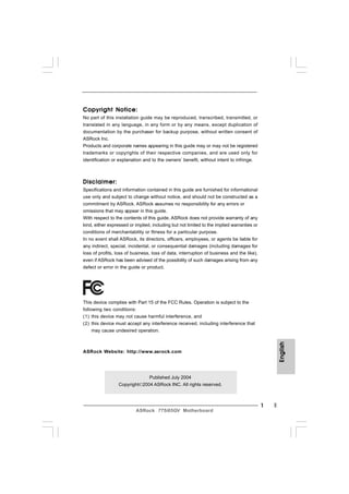
SlideShare une entreprise Scribd logo
1  sur  84
Télécharger pour lire hors ligne
Copyright Notice:
No part of this installation guide may be reproduced, transcribed, transmitted, or
translated in any language, in any form or by any means, except duplication of
documentation by the purchaser for backup purpose, without written consent of
ASRock Inc.
Products and corporate names appearing in this guide may or may not be registered
trademarks or copyrights of their respective companies, and are used only for
identification or explanation and to the owners’ benefit, without intent to infringe.


Disclaimer:
Specifications and information contained in this guide are furnished for informational
use only and subject to change without notice, and should not be constructed as a
commitment by ASRock. ASRock assumes no responsibility for any errors or
omissions that may appear in this guide.
With respect to the contents of this guide, ASRock does not provide warranty of any
kind, either expressed or implied, including but not limited to the implied warranties or
conditions of merchantability or fitness for a particular purpose.
In no event shall ASRock, its directors, officers, employees, or agents be liable for
any indirect, special, incidental, or consequential damages (including damages for
loss of profits, loss of business, loss of data, interruption of business and the like),
even if ASRock has been advised of the possibility of such damages arising from any
defect or error in the guide or product.


This device complies with Part 15 of the FCC Rules. Operation is subject to the
following two conditions:
(1) this device may not cause harmful interference, and
(2) this device must accept any interference received, including interference that
     may cause undesired operation.
                                                                                                English


ASRock Website: http://www.asrock.com


                               Published July 2004
                  Copyright©2004 ASRock INC. All rights reserved.


                                                                                            1
                           ASRock 775i65GV Motherboard
Layout
              Motherboard Layout


              1    PS2_USB_PWR1 Jumper                              16   System Panel Header (PANEL1)
              2    775-Pin CPU Socket                               17   Infrared Module Header (IR1)
              3    North Bridge Controller                          18   Clear CMOS Jumper (CLRCMOS0)
              4    CPU Fan Connector (CPU_FAN1)                     19   Floppy Connector (FLOPPY1)
              5    184-pin DDR DIMM Slots (DDR1- 2, Dual Channel)   20   AMR Slot (AMR1)
              6    ATX Power Connector (ATXPWR1)                    21   Internal Audio Connector: CD1 (Black)
              7    Primary IDE Connector (IDE1, Blue)               22   Internal Audio Connector: AUX1 (White)
English


              8    Secondary IDE Connector (IDE2, Black)            23   PCI Slots (PCI1- 3)
              9    ASRock Graphics Interface Slot (1.5V_AGP1)       24   JR1 Jumper / JL1 Jumper
              10   South Bridge Controller                          25   Front Panel Audio Header (AUDIO1)
              11   Secondary Serial ATA Connector (SATA2)           26   COM Port Header (COM1)
              12   Primary Serial ATA Connector (SATA1)             27   Shared USB 2.0 Header (USB4_5, Blue)
              13   Chassis Speaker Header (SPEAKER 1)               28   BIOS FWH Chip
              14   Chassis Fan Connector (CHA_FAN1)                 29   FSB Select Jumper (FSB1)
              15   USB 2.0 Header (USB67, Blue)                     30   ATX 12V Connector (ATX12V1)


          2
                                          ASRock 775i65GV Motherboard
ASRock I/O Plus TM


 1   Parallel Port                       7    USB 2.0 Ports (USB01)
 2   RJ-45 Port                          8    USB 2.0 Ports (USB23)
 3   Line In (Light Blue)                9    VGA Port
 4   Line Out (Lime)                     10   PS/2 Keyboard Port (Purple)
 5   Microphone (Pink)                   11   PS/2 Mouse Port (Green)
 6   Shared USB 2.0 Ports (USB45)


                                                                                English


                                                                            3
                         ASRock 775i65GV Motherboard
1. Introduction
              Thank you for purchasing ASRock 775i65GV motherboard, a reliable motherboard
              produced under ASRock’s consistently stringent quality control. It delivers excellent
              performance with robust design conforming to ASRock’s commitment to quality and
              endurance.
              This Quick Installation Guide contains introduction of the motherboard and step-by-
              step installation guide. More detailed information of the motherboard can be found in
              the user manual presented in the Support CD.

                          Because the motherboard specifications and the BIOS software might be
                          updated, the content of this manual will be subject to change without
                          notice. In case any modifications of this manual occur, the updated
                          version will be available on ASRock website without further notice. You
                          may find the latest memory and CPU support lists on ASRock website as
                          well. ASRock website    http://www.asrock.com


              1.1 Package Contents
              ASRock 775i65GV Motherboard
                 (Micro ATX Form Factor: 9.6-in x 8.6-in, 24.4 cm x 21.8 cm)
              ASRock 775i65GV Quick Installation Guide
              ASRock 775i65GV Support CD (including LGA 775 CPU Installation Live Demo)
              One 80-conductor Ultra ATA 66/100 IDE Ribbon Cable
              One Ribbon Cable for a 3.5-in Floppy Drive
              One Serial ATA (SATA) Data Cable
              One Serial ATA (SATA) HDD Power Cable (Optional)
              One ASRock I/O PlusTM Shield
              One COM Port Bracket
              One ASRock MR Card (Optional)
English
English
English
English
English


          4
                                       ASRock 775i65GV Motherboard
1.2 Specifications
Platform:          Micro ATX Form Factor: 9.6-in x 8.6-in, 24.4 cm x 21.8 cm
CPU:               775-Pin Socket
                   supporting Intel® Pentium® 4 / Celeron® processor (in 775-land
                   LGA package)
Chipsets:          North Bridge:
                      Intel® 865GV chipset, FSB @ 800 / 533 MHz,
                      supports Hyper-Threading Technology (see CAUTION 1)
                   South Bridge:
                      Intel® ICH5, supports SATA 1.5Gb/s
Memory:            2 DDR DIMM slots: DDR1 and DDR2
                      supports PC3200 (DDR400) / PC2700 (DDR333) /
                      PC2100 (DDR266), Max. 2GB (see CAUTION 2)
                      Dual Channel Memory Technology support
                      (see CAUTION 3)
IDE:               IDE1: ATA 100 / Ultra DMA Mode 5
                   IDE2: ATA 100 / Ultra DMA Mode 5
                   Supports up to 4 IDE devices
Serial ATA:        Supports up to 2 SATA devices at 1.5Gb/s data transfer rate.
                   (No Support for “RAID” and “Hot Plug” functions)
Floppy Port:       Supports up to 2 floppy disk drives
Audio:             5.1 channels AC’97 Audio
PCI LAN:           Speed: 802.3u (10/100 Ethernet), supports Wake-On-LAN
Hardware Monitor:CPU temperature sensing
                   Motherboard temperature sensing
                   CPU overheat shutdown to protect CPU life
                   (ASRock U-COP)(see CAUTION 4)
                   CPU fan tachometer
                   Chassis fan tachometer
                   Voltage monitoring: +12V, +5V, +3.3V, Vcore
PCI slots:         3 PCI slots with PCI Specification 2.2 (see CAUTION 5)
AMR slot:          1 slot, supports ASRock MR card (Optional)
AGI slot:          1 AGI [ASRock Graphics Interface] slot (see CAUTION 6)
USB 2.0:           8 USB 2.0 ports:
                                                                                        English


                   includes 6 default USB 2.0 ports on the rear panel,
                   plus one header to support 2 additional USB 2.0 ports
                   (see CAUTION 7)
ASRock I/O PlusTM: 1 PS/2 mouse port, 1 PS/2 keyboard port,
                   1 VGA port, 1 parallel port: ECP/EPP support,
                   6 default USB 2.0 ports,
                   1 RJ-45 port,
                   Audio Jack: Line In / Line Out / Microphone
                                                                                    5
                        ASRock 775i65GV Motherboard
COM Port:              1 COM Port Header to support a COM port module
              BIOS:                  AMI legal BIOS, Supports “Plug and Play”,
                                     ACPI 1.1 compliance wake up events,
                                     CPU frequency stepless control
                                     (only for advanced users’ reference, see CAUTION 8)
              OS:                    Microsoft® Windows® 98 SE / ME / 2000 / XP compliant


                    CAUTION!
                    1.    About the setting of “Hyper Threading Technology”, please check page 27
                          of “User Manual” in the Support CD.
                    2.    Please check the table below for the memory support frequency and its
                          corresponding CPU FSB frequency.
                            CPU FSB Frequency        Memory Support Frequency
                                   800                     DDR266, DDR320*, DDR400
                                   533                     DDR266, DDR333
                                   400                     DDR266
                          * When you use an FSB800-CPU on this motherboard, it will run at
                            DDR320 if you adopt a DDR333 memory module.
                    3.    This motherboard supports Dual Channel Memory Technology. Before you
                          implement Dual Channel Memory Technology, make sure to read the
                          installation guide of memory modules on page 12 for proper installation.
                    4.    While CPU overheat is detected, the system will automatically shutdown.
                          Before you resume the system, please check if the CPU fan on the
                          motherboard functions properly and unplug the power cord, then plug it
                          back again. To improve heat dissipation, remember to spray thermal
                          grease between the CPU and the heatsink when you install the PC system.
                    5.    Because the installed AMR card will occupy the same external connecting
                          position with the PCI card that are installed in “PCI3” slot, you will not be
                          able to install any PCI card in “PCI3” slot if an AMR card has already been
                          installed in the AMR slot.
                    6.    The AGI [ASRock Graphics Interface] slot is a special design that only
                          supports compatible AGP VGA cards. For the information of the compatible
                          AGP VGA cards, please refer to the “Supported AGP VGA Cards List” on
                          page 7 and page 8. For the proper installation of AGP VGA card, please
                          refer to the installation guide on page 13.
                    7.    Power Management for USB 2.0 works fine under Microsoft® Windows® XP
English


                          SP1 / 2000 SP4. It may not work properly under Microsoft® Windows® 98/
                          ME. Please refer to Microsoft® official document at
                          http://www.microsoft.com/whdc/hwdev/bus/USB/USB2support.mspx
                    8.    Although this motherboard offers stepless control, it is not recommended
                          to perform over-clocking. Frequencies other than the recommended CPU
                          bus frequencies may cause the instability of the system or damage the
                          CPU.


          6
                                         ASRock 775i65GV Motherboard
1.3   Supported AGP VGA Cards List
      (for Windows 2000/Windows XP)

      I. AGP 4X
          Graphics Chip                Model Name
             Vendor
             n-VIDIA                   ASUS AGP-V7100
                                       ASUS AGP-V7100PRO
                                       ASUS AGP-V7100 MAGIC / 32M
                                       ASUS AGP-V7700Ti
                                       ASUS AGP-V8170DDR
                                       ASUS AGP-V8170SE / LP
                                       ASUS AGP-V8200 T2
                                       ASUS AGP-V8200 T5
                                       ASUS AGP-V8440
                                       ASUS AGP-V8460 Ultra
                                       GAINWARD- GF3-TI500/64M
                                       GAINWARD- GF3-TI500/128M
                                       Inno3D GeForce2 MX400
                                       Leadtek WinFast A170 TH
                                       Leadtek WinFast A170 DDR
                                       Leadtek WinFast A250LE TD
                                       Leadtek WinFast GeForce2 MX MX64
                                       Leadtek WinFast GeForce2 H MX400
                                       MSI- GF4-MX440SE
                                       PROLINK GF4-MX440
                                       SPARKLE GF4-MX440
             ATI                       Gigabyte GV-AP64D
                                       Gigabyte GV-AP64D-H
                                       Gigabyte GV-AR64S-H
                                       POWERCOLOR RADEON 9000
                                       POWERCOLOR RADEON 9100
                                       TRANSCEND TS64MVDR7
             SiS                       SYNNEX GCM-SiS315EA32


      For the latest updates of the supported AGP VGA cards list, please visit
      ASRock website for details.
                                                                                     English


      ASRock website: http://www.asrock.com/support/index.htm


                                                                                 7
                          ASRock 775i65GV Motherboard
II. AGP 8X
                  Graphics Chip                Model Name
                     Vendor
                     n-VIDIA                   ALBATRON GF4-MX440 64M
                                               AOPEN Aeolus FX5600S-DV128
                                               AOPEN Aeolus FX5200-V128
                                               ASUS AGP-V9180
                                               ASUS AGP-V9280 VIEDO SUITE
                                               ASUS AGP-V9520 MAGIC/T
                                               ASUS V9900
                                               ASUS V9900 ULTRA
                                               ELSA-GLADIC 518
                                               ELSA-GLADIC 518 P
                                               Inno3D GeForce FX5600
                                               LEADTEK A280 LE
                                               LEADTEK A340TDH
                                               MSI Ti4800SE-VTD8X
                                               PALIT GF4 MX440 8X 64MB
                                               PROLINK GeForceFX5900
                                               PROLINK GF4-TI4200
                                               SPARKLE GF4-MX440-8X
                     ATI                       CLUB3D ATI R9800
                                               Gigabyte GV R9000 PRO
                                               Gigabyte RADEON 9500
                                               Gigabyte RADEON 9700 PRO
                                               POWER COLOR 9200
                                               SAPHIRE RADEON 9200-128MB
                     SiS                       POWER COLOR XABRE600


              For the latest updates of the supported AGP VGA cards list, please visit
              ASRock website for details.
              ASRock website: http://www.asrock.com/support/index.htm
English


          8
                                  ASRock 775i65GV Motherboard
2. Installation
                     Pre-installation Precautions
       Take note of the following precautions before you install mother-
       board components or change any motherboard settings.


       1. Unplug the power cord from the wall socket before touching any
          component. Failure to do so may cause severe damage to the
          motherboard, peripherals, and/or components.
       2. To avoid damaging the motherboard components due to static
          electricity, NEVER place your motherboard directly on the carpet
          or the like. Also remember to use a grounded wrist strap or touch
          a safety grounded object before you handle components.
       3. Hold components by the edges and do not touch the ICs.
       4. Whenever you uninstall any component, place it on a grounded
          antstatic pad or in the bag that comes with the component.
       5. When placing screws into the screw holes to secure the
          motherboard to the chassis, please do not over-tighten the
          screws! Doing so may damage the motherboard.


2.1 CPU Installation
For the installation of Intel 775-Pin CPU,
please follow the steps below.


                                                             775-Pin Socket Overview


             Before you insert the 775-Pin CPU into the socket, please check if the
             CPU surface is unclean or if there is any bent pin on the socket. Do
                                                                                            English


             not force to insert the CPU into the socket if above situation is found.
             Otherwise, the CPU will be seriously damaged.


                                                                                        9
                         ASRock 775i65GV Motherboard
Step 1. Open the socket:
                       Step 1-1. Disengaging the lever by depressing
                                 down and out on the hook to clear
                                 retention tab.


                          Step 1-2. Rotate the load lever to fully open po-
                                    sition at approximately 135 degrees.
                          Step 1-3. Rotate the load plate to fully open po-
                                    sition at approximately 100 degrees.


               Step 2. Insert the 775-Pin CPU:
                       Step 2-1. Hold the CPU by the edges where are
                                   marked with black lines.

                                                                                     black line


                                                                                                                black line
                          Step 2-2. Orient the CPU with IHS (Integrated
                                    Heat Sink) up. Locate Pin1 and the two
                                    orientation key notches.
                   Pin1
                                                                            Pin1
                                                                   alignment key                    alignment key
                orientation                    orientation
                key notch                      key notch


                                                                                   775-Pin Socket

                                775-Pin CPU


                                  For proper inserting, please ensure to match the two orientation key
                                  notches of the CPU with the two alignment keys of the socket.


                          Step 2-3. Carefully place the CPU into the socket
                                    by using a purely vertical motion.
                          Step 2-4. Verify that the CPU is within the socket
English


                                    and properly mated to the orient keys.


               Step 3. Remove PnP Cap (Pick and Place Cap):
                       Use your left hand index finger and thumb to
                       support the load plate edge, engage PnP cap
                       with right hand thumb and peel the cap from the
                       socket while pressing on center of PnP cap to
                       assist in removal.

          10
                                              ASRock 775i65GV Motherboard
It is recommended to use the cap tab to handle and avoid kicking off
                 the PnP cap.


Step 4. Close the socket:
        Step 4-1. Rotate the load plate onto the IHS.
        Step 4-2. While pressing down lightly on load
                  plate, engage the load lever.
        Step 4-3. Secure load lever with load plate tab
                  under retention tab of load lever.


2.2       Installation of CPU Fan and Heatsink
For proper installation, please kindly refer to the instruction manuals of
your CPU fan and heatsink.


Below is an example to illustrate the installation of the heatsink for 775-Pin CPU.
Step 1. Apply thermal interface material onto center
         of IHS on the socket surface.


Step 2.    Place the heatsink onto the socket. Ensure
           fan cables are oriented on side closest to the
           CPU fan connector on the motherboard
           (CPU_FAN1, see page 10, No. 4).
Step 3.    Align fasteners with the motherboard
           throughholes.
Step 4.    Rotate the fastener clockwise, then press
           down on fastener caps with thumb to install
           and lock. Repeat with remaining fasteners.


                 If you press down the fasteners without rotating them clockwise,
                                                                                             English


                 the heatsink cannot be secured on the motherboard.


Step 5.    Connect fan header with the CPU fan
           connector on the motherboard.
Step 6.    Secure excess cable with tie-wrap to ensure
           cable does not interfere with fan operation or
           contact other components.


                                                                                        11
                           ASRock 775i65GV Motherboard
2.3 Installation of Memory Modules (DIMM)
               775i65GV motherboard provides two 184-pin DDR (Double Data Rate) DIMM slots,
               and supports Dual Channel Memory Technology. For dual channel configuration,
               you always need to install two identical (the same brand, speed, size and chip-
               type) memory modules in the DDR DIMM slots to activate Dual Channel Memory
               Technology. Otherwise, it will operate at single channel mode.

                              If you install only one memory module or two non-identical memory
                              modules, it is unable to activate the Dual Channel Memory Technology.


               Installing a DIMM

                              Please make sure to disconnect power supply before adding or
                              removing DIMMs or the system components.


               Step 1.   Unlock a DIMM slot by pressing the retaining clips outward.
               Step 2.   Align a DIMM on the slot such that the notch on the DIMM matches the break
                         on the slot.


                              The DIMM only fits in one correct orientation. It will cause permanent
English


                              damage to the motherboard and the DIMM if you force the DIMM into
                              the slot at incorrect orientation.


               Step 3.   Firmly insert the DIMM into the slot until the retaining clips at both ends fully
                         snap back in place and the DIMM is properly seated.


          12
                                         ASRock 775i65GV Motherboard
2.4 Expansion Slots (PCI, AMR, and AGI Slots)
There are 3 PCI slots, 1 AMR slot, and 1 AGI slot on this motherboard.
PCI slots: PCI slots are used to install expansion cards that have the 32-bit PCI
           interface.

                Because the installed AMR card will occupy the same external
                connecting position with the PCI card installed in “PCI3” slot, you will
                no be able to install any PCI card in “PCI3” slot if an AMR card has
                already been installed in the AMR slot.


AMR slot: AMR slot is used to insert an ASRock MR card (optional) with v.92
          Modem functionality.
AGI slot: The AGI [ASRock Graphics Interface] slot is a special design that only
          supports compatible AGP VGA cards. For the information of the compat-
          ible AGP VGA cards, please refer to the “Supported AGP VGA Cards List”
          on page 7 and page 8.

                To install the system with an add-on AGP VGA card, you must make
                sure to install the driver of add-on AGP VGA card before you install
                the onboard VGA driver. If the onboard VGA driver has already been
                installed before you install the add-on AGP VGA card, the system will
                automatically set the onboard VGA as the primary graphics adapter. In
                that case, if you want to install the add-on AGP VGA card, you need
                to remove the onboard VGA driver first, and then install the add-on
                AGP VGA card and its driver. For the detailed instruction, please refer
                to the documents in the Support CD, “AGI Slot Installation Guide (for
                Windows 2000)” and “AGI Slot Installation Guide (for Windows XP)”,
                which are located in the folder at the following path:
                .. Easy Dual Monitor


Installing an expansion card
Step 1.   Before installing the expansion card, please make sure that the power
          supply is switched off or the power cord is unplugged. Please read the
          documentation of the expansion card and make necessary hardware
          settings for the card before you start the installation.
                                                                                                English


Step 2.   Remove the bracket facing the slot that you intend to use. Keep the screws
          for later use.
Step 3.   Align the card connector with the slot and press firmly until the card is
          completely seated on the slot.
Step 4.   Fasten the card to the chassis with screws.


                                                                                           13
                           ASRock 775i65GV Motherboard
2.5 Easy Dual Monitor Feature
               Thanks to ASRock patented AGI8X Technology, this motherboard supports Easy
               Dual Monitor upgrade. With the internal onboard VGA and the external add-on AGP
               VGA card, you can easily enjoy the benefits of Dual Monitor feature. For the
               detailed instruction, please refer to the document at the following path in the
               Support CD:      .. Easy Dual Monitor


               2.6 Jumpers Setup
               The illustration shows how jumpers are
               setup. When the jumper cap is placed on
               pins, the jumper is “SHORT”. If no jumper cap
               is placed on the pins, the jumper is “OPEN”.
               The illustration shows a 3-pin jumper whose
               pin1 and pin2 are “SHORT” when jumper cap
               is placed on these 2 pins.                         Short        Open

               Jumper                          Setting                  Description
               PS2_USB_PWR1                                         Short pin2, pin3 to enable
               (see p.2 No. 1)                                      +5VSB (standby) for PS/2
                                                                    or USB wake up events.
               Note: To select +5VSB, it requires 2 Amp and higher standby current provided by
                        power supply.


               FSB Select Jumper
               (see p.2 No. 29)
                                         NORMAL           TEST

               Note: The default setting of the FSB Select jumper is “NORMAL” (short pin1, pin2).
                     For the system’s stability, please keep the default setting.


               JR1 / JL1 Jumpers
               (see p.2 No. 24)


               Note: If JR1 and JL1 Jumpers are short, both the front panel and the rear panel
English


                     audio connectors can work.


          14
                                        ASRock 775i65GV Motherboard
Clear CMOS
(CLRCMOS0)
(see p.2 No. 18)
                           2-pin jumper


Note: CLRCMOS0 allows you to clear the data in CMOS. The data in CMOS includes
      system setup information such as system password, date, time, and system
      setup parameters. To clear and reset the system parameters to default setup,
      please turn off the computer and unplug the power cord from the power
      supply. After waiting for 15 seconds, use a jumper cap to short the Clear CMOS
      jumper for 5 seconds. After shorting the Clear CMOS jumper, please remove
      the jumper cap. However, please do not clear the CMOS right after you update
      the BIOS. If you need to clear the CMOS when you just finish updating the BIOS,
      you must boot up the system first, and then shut it down before you do the
      clear-CMOS action.


                                                                                             English


                                                                                        15
                         ASRock 775i65GV Motherboard
2.7 Onboard Headers and Connectors

                                  Onboard headers and connectors are NOT jumpers. Do NOT place
                                  jumper caps over these headers and connectors. Placing jumper caps
                                  over the headers and connectors will cause permanent damage of the
                                  motherboard!


               FDD connector
               (33-pin FLOPPY1)
               (see p.2 No. 19)
                                                                                          the red-striped side to Pin1


               Note: Make sure the red-striped side of the cable is plugged into Pin1 side of the
                     connector.


                         Primary IDE connector (Blue)           Secondary IDE connector (Black)
                         (39-pin IDE1, see p.2 No. 7)           (39-pin IDE2, see p.2 No. 8)


                  connect the blue end                                               connect the black end
                    to the motherboard                                               to the IDE devices
                                               80-Conductor ATA 66/100 cable

               Note: If you use only one IDE device on this motherboard, please set the IDE
                     device as “Master”. Please refer to the instruction of your IDE device vendor
                     for the details. Besides, to optimize compatibility and performance, please
                     connect your hard disk drive to the primary IDE connector (IDE1, blue) and
                     CD-ROM to the secondary IDE connector (IDE2, black).

               Serial ATA Connectors                    SATA2                   These two Serial ATA (SATA)
               (SATA1: see p.2 No. 12)                                          connectors support SATA data
               (SATA2: see p.2 No. 11)                                          cables for internal storage
                                                                                devices. The current SATA
                                                        SATA1
                                                                                interface allows up to 1.5 Gb/s
English


                                                                                data transfer rate.


               Serial ATA (SATA)                                                Either end of the SATA data cable
               Data Cable                                                       can be connected to the SATA
                                                                                hard disk or the SATA connector
                                                                                on the motherboard.


          16
                                                ASRock 775i65GV Motherboard
Serial ATA (SATA)                                           Please connect the black end of
Power Cable                                                 SATA power cable to the power
(Optional)           connect to the SATA                    connector on each drive. Then
                    HDD power connector                     connect the white end of SATA
                                           connect to the
                                           power supply     power cable to the power
                                                            connector of the power supply.


USB 2.0 Header                                              ASRock I/O PlusTM accommo-
(9-pin USB67)                                               dates 6 default USB 2.0 ports. If
(see p.2 No. 15)                                            those USB 2.0 ports on the I/O
                                                            panel are not sufficient, this
                                                            USB 2.0 header is available to
                                                            support 2 additional USB 2.0
                                                            ports.


Shared USB 2.0 Header                                       This USB4_5 connector is shared
(9-pin USB4_5)                                              with the USB 2.0 ports 4,5 on
(see p.2 No. 27)                                            ASRock I/O PlusTM. When using
                                                            the front panel USB ports by
                                                            attaching the front panel USB
                                                            cable to this connector
                                                            (USB4_5), the USB ports 4,5 on
                                                            ASRock I/O PlusTM will not be able
                                                            to function.


Infrared Module Header                                      This header supports an
(5-pin IR1)                                                 optional wireless transmitting
(see p.2 No. 17)                                            and receiving infrared module.


Internal Audio Connectors                                   These connectors allow you
(4-pin CD1, 4-pin AUX1)                                     to receive stereo audio input
(CD1: see p.2 No. 21)                                       from sound sources such as
(AUX1: see p.2 No. 22)               CD1          AUX1      a CD-ROM, DVD-ROM, TV
                                                            tuner card, or MPEG card.
                                                                                                      English


Front Panel Audio Header                                    This is an interface for front
(9-pin AUDIO1)                                              panel audio cable that allows
(see p.2 No. 25)                                            convenient connection and
                                                            control of audio devices.


                                                                                                 17
                                ASRock 775i65GV Motherboard
System Panel Header                                       This header accommodates
               (9-pin PANEL1)                                            several system front panel
               (see p.2 No. 16)                                          functions.


               Chassis Speaker Header                                    Please connect the chassis
               (4-pin SPEAKER 1)                                         speaker to this header.
               (see p.2 No. 13)


               Chassis Fan Connector                                     Please connect a chassis fan
               (3-pin CHA_FAN1)                                          cable to this connector and
               (see p.2 No. 14)                                          match the black wire to the
                                                                         ground pin.


               CPU Fan Connector                                         You may connect either a 3-pin
               (4-pin CPU_FAN1)                                          or a 4-pin CPU fan cable to this
               (see p.2 No. 4)                                           connector, then match the black
                                                                         wire to the ground pin.
               Note: If you use a 3-pin CPU fan cable, insert it to the connector by aligning it with the pins
                       “GND”, “+12V”, and “CPU_FAN_SPEED”.


               ATX Power Connector                                       Please connect an ATX power
               (20-pin ATXPWR1)                                          supply to this connector.
               (see p.2 No. 7)


               COM Port Header                                           This COM port header is used
               (9-pin COM1)                                              to support a COM port module.
               (see p.2 No. 23)


               ATX 12V Connector                                         Please note that it is necessary
English


               (4-pin ATX12V1)                                           to connect a power supply with
               (see p.2 No. 30)                                          ATX 12V plug to this connector
                                                                         so that it can provides sufficient
                                                                         power. Failing to do so will cause
                                                                         the failure to power up.


          18
                                          ASRock 775i65GV Motherboard
2.8            AT (SAT
        Serial ATA (SATA) Hard Disks Installation
This motherboard adopts Intel ICH5 south bridge chipset that supports Serial ATA
(SATA) hard disks. You may install SATA hard disks on this motherboard for
internal storage devices. This section will guide you to install the SATA hard disks.


STEP 1: Install the SATA hard disks into the drive bays of your chassis.
STEP 2: Connect the SATA power cable to the SATA hard disk.
STEP 3: Connect one end of the SATA data cable to the motherboard’s SATA
        connector.
STEP 4: Connect the other end of the SATA data cable to the SATA hard disk.

              Before you install OS into the SATA hard disk, you need to check and
              ensure the configuration of the OnBoard IDE Operate Mode option in
              BIOS setup is correct according to the condition of your system. For
              the configuration details, please refer to the instruction on page 27 of
              “User Manual” in the Support CD.


3. BIOS Information
The BIOS Setup Utility is stored in the BIOS FWH chip. When you start up the
computer, please press <F2> during the Power-On-Self-Test (POST) to enter the
BIOS Setup Utility; otherwise, POST continues with its test routines. If you wish to
enter the BIOS Setup Utility after POST, please resume the system by pressing <Ctl>
+ <Alt> + <Delete>, or pressing the reset button on the system chassis. For the
detailed information about the BIOS Setup Utility, please refer to the User Manual
(PDF file) contained in the Support CD.
                                                                                              English


                                                                                         19
                          ASRock 775i65GV Motherboard
Support
               4. Software Suppor t CD information
               This motherboard supports various Microsoft® Windows® operating systems: 98 SE/
               ME / 2000 / XP. The Support CD that came with the motherboard contains necessary
               drivers and useful utilities that will enhance motherboard features.
               To begin using the Support CD, insert the CD into your CD-ROM drive. It will display
               the Main Menu automatically if “AUTORUN” is enabled in your computer. If the Main
               Menu does not appear automatically, locate and double-click on the file
               “ASSETUP.EXE” from the “BIN” folder in the Support CD to display the menus.


                  “PC-DIY Live Demo”
                  ASRock presents you a multimedia PC-DIY live demo, which shows you a
                  step-by-step guide to install your own PC system. To see this demo program,
                  you can run Microsoft® Media Player® to play the file, which can be found
                  through the following path:
                  .. MPEGAV  AVSEQ01.DAT


                  “LGA 775 CPU Installation Live Demo”
                  This motherboard is equipped with Intel LGA 775 socket, which is a new CPU
                  socket interface that Intel has released. Since it has several tiny pins, whcih
                  are easily to be damaged by improper handling, ASRock sincerely presents
                  you a clear installation guide through this “LGA 775 CPU Installation Live
                  Demo”. We hope you may check this live demo program before you start the
                  installation of LGA 775 CPU in order to reduce the risks of CPU and
                  motherboard damages caused by any improper handling. To see this Live
                  Demo, you can run Microsoft® Media Player® to play the file. You may find this
                  Live Demo in the motherboard’s Support CD through the following path:
                  .. MPEGAV  LGA775INST.DAT
English


          20
                                       ASRock 775i65GV Motherboard
1. Einführung
Wir danken Ihnen für den Kauf des ASRock 775i65GV Motherboard, ein zuverlässiges
Produkt, welches unter den ständigen, strengen Qualitätskontrollen von ASRock
gefertigt wurde. Es bietet Ihnen exzellente Leistung und robustes Design, gemäß der
Verpflichtung von ASRock zu Qualität und Halbarkeit.
Diese Schnellinstallationsanleitung führt in das Motherboard und die schrittweise
Installation ein. Details über das Motherboard finden Sie in der
Bedienungsanleitung auf der Support-CD.

             Da sich Motherboard-Spezifikationen und BIOS-Software verändern können,
             kann der Inhalt dieses Handbuches ebenfalls jederzeit geändert werden. Für
             den Fall, dass sich Änderungen an diesem Handbuch ergeben, wird eine neue
             Version auf der ASRock-Website, ohne weitere Ankündigung, verfügbar sein.
             Die jeweils neueste Liste der unterstützten Speichertypen CPUs finden Sie
             ebenfalls auf der Webseite von ASRock.
             ASRock-Website: http://www.asrock.com


1.1 Kartoninhalt
ASRock 775i65GV Motherboard
    (Micro ATX-Formfaktor: 24.4 cm x 21.8 cm; 9.6 Zoll x 8.6 Zoll)
ASRock 775i65GV Schnellinstallationsanleitung
ASRock 775i65GV Support-CD (einschl. LGA 775 CPU Installation Live-Demo)
Ein 80-adriges Ultra-ATA 66/100 IDE-Flachbandkabel
Ein Flachbandkabel für ein 3,5-Zoll-Diskettenlaufwerk
Ein Seriell-ATA- (SATA) Datenkabel
Ein Seriell-ATA (SATA) Festplattennetzkabel (Option)
Ein ASRock I/O PlusTM Shield
Ein COM Port-Anschlusshalter
Ein ASRock MR-Karte (Option)


1.2 Spezifikationen
Plattform:              Micro ATX-Formfaktor: 24.4 cm x 21.8 cm; 9.6 Zoll x 8.6 Zoll
                                                                                               Deutsch


CPU:                    Unterstützt 775-Pin Socket für Intel Pentium 4 / Celeron
                        Prozessor (in 775-land LGA Paket)
Chipsatz:               North Bridge:
                            Intel® 865GV-Chipsatz, FSB @ 800 / 533 MHz,
                            unterstützt Hyper-Threading Technology
                            (siehe VORSICHT 1)
                        South Bridge:
                            Intel® ICH5, unterstützt SATA 1.5Gb/s

                                                                                          21
                           ASRock 775i65GV Motherboard
RAM:                2 DDR Slots: DIMM1 und DIMM2
                                       Unterstützt PC3200 (DDR400) /PC2700 (DDR333) /
                                       PC2100 (DDR266), Max. 2GB (siehe VORSICHT 2)
                                       Unterstützung von Dual-Kanal-Speichertechnologi
                                      (siehe VORSICHT 3)
               HDD:                IDE1: ATA 100 / Ultra DMA Mode 5
                                   IDE2: ATA 100 / Ultra DMA Mode 5
                                   Unterstützt bis 4 IDE-Geräte
               Seriell-ATA:        2 SATA-Anschlüsse, unterstützt bis 1.5 Gb/s
                                   Datenübertragungsrate
                                   (Unterstützt keine “RAID”- und “Hot-Plug”-Funktionen)
               FDD:               Unterstützt bis 2 Diskettenlaufwerke
               Audio:             5.1 Kanal AC’97 Audio
               PCI LAN:           Speed: 802.3u (10/100 Ethernet), unterstützt Wake-On-LAN
               Hardware Monitor:  CPU Temperaturmessung,
                                  Motherboardtemperaturerkennung,
                                  CPU Shutdown bei Überhitzung, schützt die CPU vor dem
                                  Hitzetod (ASRock U-COP)(siehe VORSICHT 4),
                                  Rotationskontrolle für CPU-Lüfter,
                                  Rotationskontrolle für Gehäuse-Lüfter,
                                  Spannungsüberwachung: +12V, +5V, +3.3V, Vcore
               PCI-Slots:         3 Slots nach PCI-Spezifikation 2.2 (siehe VORSICHT 5)
               AMR-Slot:          Unterstützt ASRock MR-Karten (Option)
               AGI-Slot:          1x AGI-Slot [ASRock Graphics Interface] (siehe VORSICHT 6)
               USB 2.0:           8 USB 2.0-Anschlüsse:
                                  einschließlich 6 Standard-USB 2.0-Anschlüsse auf der
                                  Rückseite, plus einem Header zur Unterstützung 2
                                  zusätzlicher USB 2.0-Anschlüsse (siehe VORSICHT 7)
               ASRock I/O PlusTM: 1 PS/2-Mausanschluss, 1 PS/2-Tastaturanschluss,
                                  1 VGA Port, 1 paralleler port: Unterstützung für ECP / EPP,
                                  6 hintere USB 2.0-Ports, 1 RJ 45 port,
                                  Audioanschlüsse: Line In / Line Out / Mikrofon
               COM-Anschluss: 1 COM-Anschluss-Header für ein COM-Anschlussmodul
               BIOS:              AMI legal BIOS mit Unterstützung für “Plug and Play”,
Deutsch


                                  ACPI 1.1-Weckfunktionen,
                                  Schrittloser CPU-Frequenz-Kontrolle (Nur für erfahrene
                                  Anwender empfohlen, siehe VORSICHT 8)
               Betriebssysteme: Unterstützt Microsoft® Windows® 98SE / ME / 2000 / XP


          22
                                      ASRock 775i65GV Motherboard
VORSICHT!
1.   Die Einstellung der “Hyper-Threading Technology”, finden Sie auf Seite
     27 des auf der Support-CD enthaltenen Benutzerhandbuches
     beschrieben.
2.   Die unterstützten Arbeitsspeicherfrequenzen und die entsprechende
     CPU FSB-Frequenz entnehmen Sie bitte der nachstehenden Tabelle.
      CPU FSB-Frequenz          Unterstützte Arbeitsspeicherfrequenz
             800                     DDR266, DDR320*, DDR400
             533                     DDR266, DDR333
             400                     DDR266
     * Bei Verwendung einer FSB800-CPU auf diesem Motherboard läuft es mit
      DDR320, wenn Sie ein DDR333-Speichermodul verwenden.
3.   Dieses Motherboard unterstützt Dual-Kanal-Speichertechnologie. Vor
     Implementierung der Dual-Kanal-Speichertechnologie müssen Sie die
     Installationsanleitung für die Speichermodule auf Seite 28 zwecks richtiger
     Installation gelesen haben.
4.   Wird eine Überhitzung der CPU registriert, führt das System einen
     automatischen Shutdown durch. Bevor Sie das System neu starten, prüfen
     Sie bitte, ob der CPU-Lüfter am Motherboard richtig funktioniert, und
     stecken Sie bitte den Stromkabelstecker aus und dann wieder ein. Um die
     Wärmeableitung zu verbessern, bitte nicht vergessen, etwas Wärmeleitpaste
     zwischen CPU und Kühlkörper zu sprühen.
5.   Da die installierte AMR-Karte die gleiche externe Anschlussposition wie
     die im “PCI3”-Steckplatz installierte PCI-Karte belegt, können Sie keine
     PCI-Karte im “PCI3”-Steckplatz installieren, wenn bereits eine AMR-
     Karte im AMR-Steckplatz installiert ist.
6.   Der AGI- [ASRock Graphics Interface] Steckplatz ist so ausgelegt, dass
     nur kompatible AGP-Grafikkarten unterstützt werden. Informationen über
     kompatible AGP VGA-Karten finden Sie in der “Liste unterstützter AGP
     VGA-Karten” auf den Seiten 7 und 8. (Nur Englisch) Die richtige
     Installation der AGP-Grafikkarte ist in der Installationsanleitung auf
     Seite 29 angegeben.
7.   Das Power Management für USB 2.0 arbeitet unter Microsoft® Windows®
     XP SP1/2000 SP4 einwandfrei. Unter Microsoft® Windows® 98/ME
     könnte es dagegen zu Störungen kommen. Bitte lessen Sie hierzu das
     offizielle Microsoft-Dokument, welches Sie unter folgender Adresse
                                                                                        Deutsch


     finden:
     http://www.microsoft.com/whdc/hwdev/bus/USB/USB2support.mspx
8.   Obwohl dieses Motherboard stufenlose Steuerung bietet, wird Over-
     clocking nicht empfohlen. Frequenzen, die über den für den jeweiligen
     Prozessor vorgesehenen liegen, können das System instabil werden
     lassen oder die CPU beschädigen.


                                                                                   23
                    ASRock 775i65GV Motherboard
2. Installation
                              Sicherheitshinweise vor der Montage
                      Bitte nehmen Sie die folgende Sicherheitshinweise zur Kenntnis, bevor Sie das
                      Motherboard einbauen oder Veränderungen an den Einstellungen vornehmen.


                      1.   Trennen Sie das System vom Stromnetz, bevor Sie eine ystemkomponente
                           berühren, da es sonst zu schweren Schäden am Motherboard oder den
                           sonstigen internen, bzw. externen omponenten kommen kann.
                      2.   Um Schäden aufgrund von statischer Elektrizität zu vermeiden, das
                           Motherboard NIEMALS auf einen Teppich o.ä.legen. Denken Sie außerem
                           daran, immer ein geerdetes Armband zu tragen oder ein geerdetes Objekt
                           aus Metall zu berühren, bevor Sie mit Systemkomponenten hantieren.
                      3.   Halten Sie Komponenten immer an den Rändern und vermeiden Sie
                           Berührungen mit den ICs.
                      4.   Wenn Sie Komponenten ausbauen, legen Sie sie immer auf eine
                           antistatische Unterlage, oder zurück in die Tüte, mit der die Komponente
                           geliefert wurde.
                      5.   Wenn Sie das Motherboard mit den Schrauben an dem Computergehäuse
                           befestigen, überziehen Sie bitte die Schrauben nicht! Das Motherboard kann
                           sonst beschädigt werden.


               2.1 CPU Installation
                                                                     (Ladeplatte)
               Für die Installation des Intel 775-Pin CPU                                         (Sockel)

               führen Sie bitte die folgenden Schritte durch.
                                                                    (Kontaktreihe)


                                                                              775-Pin Sockel Übersicht
Deutsch


                               Bevor Sie die 775-Pin CPU in den Sockel sitzen, prüfen Sie bitte,
                               ob die CPU-Oberfläche sauber ist und keine der Kontakte verbogen
                               sind. Setzen Sie die CPU nicht mit Gewalt in den Sockel, dies kann
                               die CPU schwer beschädigen.


          24
                                        ASRock 775i65GV Motherboard
Schritt 1. Öffnen Sie den Sockel:
           Schritt 1-1. Öffnen Sie den Hebel, indem
                        Sie ihn nach unten drücken und
                        aushaken.


            Schritt 1-2. Drehen Sie den Ladehebel, bis
                         er in geöffneter Position steht,
                         ca. 135 Grad.
            Schritt 1-3. Drehen Sie die Ladeplatte, bis
                         sie in geöffneter Position steht,
                         ca. 100 Grad.


Schritt 2. 775-Pin CPU einstecken:
           Schritt 2-1. Halten Sie die CPU an den mit
                                                                         Schwarze Linie


                                                                                                            Schwarze Linie
                        schwarzen Linien
                        gekennzeichneten Seiten.


            Schritt 2-2. Halten Sie das Teil mit dem IHS
                         (Integrated Heat Sink –
                         integrierter Kühlkörper) nach
                         oben. Suchen Sie Pin 1 und die
                         zwei
                         Orientierungseinkerbungen.
                                                          Pin1
        Pin1                            Ausrichtungsmarkierung                            Ausrichtungsmarkierung

Orientierungskerbe                  Orientierungskerbe

                                                                 775-Pin Sockel


                      775-Pin CPU

                     Um die CPU ordnungsgemäß einsetzen zu können, richten Sie die
                                                                                                                                  Deutsch


                     zwei Orientierungskerben der CPU mit den beiden Markierungen des
                     Sockels aus.


            Schritt 2-3. Drücken Sie die CPU vorsichtig
                         in vertikaler Richtung in den
                         Sockel.


                                                                                                                             25
                               ASRock 775i65GV Motherboard
Schritt 2-4. Prüfen Sie, dass die CPU
                                      ordnungsgemäß im Sockel sitzt
                                      und die Orientierungskerben
                                      einwandfrei in den
                                      entsprechenden Auskerbungen
                                      sitzen.


               Schritt 3. PnP-Kappe entfernen (Pick and Place-Kappe):
                          Halten Sie den Rand der Ladeplatte mit
                          Zeigefinger und Daumen Ihrer linken Hand,
                          halten Sie die PnP-Kappe mit dem Daumen
                          der rechten Hand und ziehen Sie die Kappe
                          vom Sockel während Sie auf die Mitte der
                          Kappe drücken, um ein Entfernen zu
                          erleichtern.

                              Verwenden Sie beim Entfernen die Kappenlasche und vermeiden Sie
                              ein Abreißen der PnP-Kappe.


               Schritt 4. Sockel schließen:
                          Schritt 4-1. Drehen Sie die Ladeplatte auf
                                       den Kühlkörper (IHS).
                          Schritt 4-2. Drücken Sie leicht auf die
                                       Ladeplatte und schließen Sie
                                       den Ladehebel.
                          Schritt 4-3. Sichern Sie Ladehebel und
                                       Ladeplatte mithilfe des
                                       Hebelverschlusses.
Deutsch


          26
                                       ASRock 775i65GV Motherboard
2.2 Installation des CPU-Lüfters und Kühlkörpers
Für Installationshinweise, siehe Betriebsanleitung Ihres CPU-Lüfters
und Kühlkörpers.
Unten stehend ein Beispiel zur Installation eines Kühlkörpers für den 775-Pin CPU.
                                                           (Tragen Sie Wärmeleitmaterial auf. )
Schritt 1. Geben Sie Wärmeleitmaterial auf die Mitte
           des IHS, auf die Sockeloberfläche.


                                                           (Lüfterkabel auf der Seite am nächsten
                                                           zum Anschluss des Motherboards)
Schritt 2. Setzen Sie den Kühlkörper auf den Sockel.
           Prüfen Sie, dass die Lüfterkabel auf der
           Seite am nächsten zum CPU-Lüfter-
           Anschluss des Motherboards verlaufen
           (CPU_FAN1, siehe Seite 2, Nr. 8).
Schritt 3. Richten Sie Verbindungselemente und              (Schlitze der Verbindungselemente
                                                            nach außen)
           Löcher im Motherboard aus.
                                                            (Nach unten drücken (4 Stellen))
Schritt 4. Drehen Sie die Verbindungselemente im
           Uhrzeigersinn und drücken Sie mit dem
           Daumen auf die Kappen der Elemente zum
           Feststellen. Wiederholen Sie dies mit den
           anderen Verbindungselementen.

               Wenn Sie die Verbindungselemente nur drücken, ohne sie im
               Uhrzeigersinn zu drehen, wird der Kühlkörper nicht ordnungsgemäß
               am Motherboard befestigt.


Schritt 5. Schließen Sie den Lüfter an den CPU-
           Lüfteranschluss des Motherboards.
Schritt 6. Befestigen Sie überschüssiges Kabel mit
           Band, um eine Störung des Lüfters oder
           Kontakt mit anderen Teilen zu vermeiden.
                                                                                                         Deutsch


                                                                                                    27
                         ASRock 775i65GV Motherboard
2.3 Installation der Speichermodule (DIMM)
               Das775i65GV Motherboard bietet zwei 184polige DDR (Double Data Rate) DIMM-
               Steckplätze und unterstützt Zweikanal-Speichertechnologie. Es müssen immer
               zwei identische Speichermodule (selbe Marke, Geschwindigkeit, Größe und Chip-
               Art) in den DDR DIMM-Steckplätzen installiert werden, um die Zweikanal-
               Speichertechnologie zu aktivieren. Andernfalls erfolgt der Betrieb im Einkanal-
               Modus.

                              Wenn Sie nur ein Speichermodul oder zwei nicht identische
                              Speichermodule installieren, kann die Zweikanal-Speichertechnologie
                              nicht aktiviert werden.


               Einsetzen eines DIMM-Moduls

                              Achten Sie darauf, das Netzteil abzustecken, bevor Sie DIMMs oder
                              Systemkomponenten hinzufügen oder entfernen.


               Schritt 1:   Öffnen Sie einen DIMM-Slot, indem Sie die seitlichen Clips nach außen
                            drücken.
               Schritt 2:   Richten Sie das DIMM-Modul so über dem Slot aus, dass das Modul mit
                            der Kerbe in den Slot passt.


                              Die DIMM-Module passen nur richtig herum eingelegt in die
Deutsch
Deutsch
Deutsch
Deutsch
Deutsch


                              Steckplätze. Falls Sie versuchen, die DIMM-Module mit Gewalt falsch
                              herum in die Steckplätze zu zwingen, führt dies zu dauerhaften
                              Schäden am Mainboard und am DIMM-Modul.


               Schritt 3:   Drücken Sie die DIMM-Module fest in die Steckplätze, so dass die
                            Halteklammern an beiden Enden des Moduls einschnappen und das
                            DIMM-Modul fest an Ort und Stelle sitzt.


          28
                                         ASRock 775i65GV Motherboard
2.4 Erweiterungssteckplätze: (PCI-, AMR-, und AGI-Slots):
Es stehen 3 PCI-, 1 AMR-, und 1 AGI-Slot auf dem 775i65GV Motherboard zur
Verfügung.
PCI-Slots: PCI-Slots werden zur Installation von Erweiterungskarten mit dem
             32bit PCI-Interface genutzt.

                Da die installierte AMR-Karte die gleiche externe Anschlussposition wie die
                im “PCI3”-Steckplatz installierte PCI-Karte belegt, können Sie keine PCI-
                Karte im “PCI3”-Steckplatz installieren, wenn bereits eine AMR-Karte im
                AMR-Steckplatz installiert ist.


AMR-Slot:     Der AMR-Steckplatz dient zur Aufnahme der ASRock MR-Karte
              (Option) mit v.92 Modem-Funktionalität.
AGI-Slot:     Der AGI- [ASRock Graphics Interface] Steckplatz ist so ausgelegt,
              dass nur kompatible AGP-Grafikkarten unterstützt werden.
              Informationen über kompatible AGP VGA-Karten finden Sie in der
              “Supported AGP VGA Cards List” (Liste unterstützter AGP VGA-
              Karten) auf den Seiten 7 und 8. (Nur Englisch)

                Zur Installation einer AGP-Zusatzkarte im System müssen Sie darauf
                achten, den Treiber der AGP-Zusatzkarte noch vor Installation des
                Treibers für das integrierte VGA zu installieren. Wenn der Treiber für
                das integrierte VGA bereits vor Installation der AGP-Zusatzkarte
                installiert ist, setzt das System das integrierte VGA automatisch als
                primären Grafikadapter ein. Wenn Sie in diesem Fall die AGP-
                Zusatzkarte installieren möchten, müssen Sie den Treiber für das
                integrierte VGA zuerst entfernen und dann die AGP-Zusatzkarte und
                ihren Treiber installieren. Eine detaillierte Anleitung finden Sie in den
                Dokumenten “AGI-Steckplatz-Installationsanleitung (für Windows
                2000)” und “AGI-Steckplatz-Installationsanleitung (für Windows XP)”,
                auf der Support-CD, die sich im Ordner des folgendes Pfades
                befinden:
                .. Easy Dual Monitor


Einbau einer Erweiterungskarte
Schritt 1:   Bevor Sie die Erweiterungskarte installieren, vergewissern Sie sich,
                                                                                                   Deutsch


             dass das Netzteil ausgeschaltet und das Netzkabel abgezogen ist.
             Bitte lesen Sie die Dokumentation zur Erweiterungskarte und nehmen
             Sie nötige Hardware-Einstellungen für die Karte vor, ehe Sie mit der
             Installation beginnen.
Schritt 2:   Entfernen Sie das Abdeckungsblech (Slotblende) von dem
             Gehäuseschacht (Slot) , den Sie nutzen möchten und behalten die
             Schraube für den Einbau der Karte.


                                                                                              29
                           ASRock 775i65GV Motherboard
Schritt 3:       Richten Sie die Karte über dem Slot aus und drücken Sie sie ohne
                                Gewalt hinein, bis sie den Steckplatz korrekt ausfüllt.
               Schritt 4:       Befestigen Sie die Karte mit der Schraube aus Schritt 2.


               2.5 “Easy Dual Monitor”
               Aufgrund der ASRock-patentierten AGI8X-Technologie unterstützt dieses
               Motherboard einen mühelosen Dual-Monitor-Upgrade. Mit dem intern integrierten
               VGA und der externen AGP-Grafikzusatzkarte können Sie die Vorteile der Dual-
               Monitor-Funktion problemlos in Anspruch nehmen. Detaillierte Anweisungen
               entnehmen Sie bitte dem Dokument im folgenden Pfad auf der Support-CD:
               .. Easy Dual Monitor


               2.6 Einstellung der Jumper
               Die Abbildung verdeutlicht, wie Jumper
               gesetzt werden. Werden Pins durch
               Jumperkappen verdeckt, ist der Jumper
               “Gebrückt”. Werden keine Pins durch
               Jumperkappen verdeckt, ist der Jumper
               “Offen”. Die Abbildung zeigt einen 3-Pin
               Jumper dessen Pin1 und Pin2 “Gebrückt”
               sind, bzw. es befindet sich eine Jumper-
               Kappe auf diesen beiden Pins.                        Gebrückt      Offen


               Jumper                           Einstellun             Beschreibung
               PS2_USB_PWR1                                            Überbrücken Sie Pin2, Pin3, um
               (siehe S.2 - No. 1)                                     +5VSB (Standby) zu setzen
                                                                       und die PS/2 oder USB-
                                                                       Weckfunktionen zu aktivieren.


               Hinweis: Um +5VSB nutzen zu können, muss das Netzteil auf dieser Leitung 2A
                        oder mehr leisten können.
Deutsch


               FSB Jumper einstellen
               (siehe S.2 - No. 29)
                                             NORMAL          TEST

               Hinweis: Die Default-Einstellung des FSB-Jumpers ist Kurzschluss von Kontakt 1
                        und 2. Bitte belassen Sie die Default-Einstellung, um die Systemstabilität
                        nicht zu beeinträchtigen.


          30
                                            ASRock 775i65GV Motherboard
JR1- / JL1-Jumper
(siehe S.2 - No. 24)


Hinweis: Wenn die JR1- und JL1- Jumper verbunden sind, können die
         Audioanschlüsse an dem Frontfeld sowie an der Rückwand arbeiten.


CMOS löschen
(CLRCMOS0)
(siehe S.2 - No. 18)         2-Pin jumper


Hinweis: CLRCMOS0 erlaubt Ihnen die Daten im CMOS zu löschen. Die Daten im
         CMOS sind Systemsetupdaten wie z.B. Systemkennwort, Datum, Uhrzeit
         und Systemsetupparameter. Um die Systemparameter zu löschen und die
         Standardparameterwerte wiederherzustellen, schalten Sie bitte den
         Computer aus und ziehen das Netzkabel aus der Steckdose heraus.
         Warten Sie 15 Sekunden und verwenden dann eine Jumpersteckbrücke,
         um den CMOS-Jumper für 5 Sekunden kurzzuschließen. Entfernen Sie
         bitte nach dem Kurzschließen des Clear CMOS-Jumper die
         Jumpersteckbrücke. Löschen Sie die CMOS-Daten nicht sofort nach dem
         Aktualisieren des BIOS. Müssen Sie die CMOS-Daten nach dem
         Aktualisieren des BIOS löschen, dann müssen Sie zuerst das System
         starten und dann ausschalten, bevor Sie das Löschen der CMOS-Daten
         vornehmen.


                                                                                    Deutsch


                                                                               31
                       ASRock 775i65GV Motherboard
2.7 Integrierte Header und Anschlüsse

                                      Integrierte Header und Anschlüsse sind KEINE Jumper. Setzen Sie KEINE
                                      Jumperkappen auf diese Header und Anschlüsse. Wenn Sie Jumperkappen
                                      auf Header und Anschlüsse setzen, wird das Motherboard unreparierbar
                                      beschädigt!


               Anschluss für das
               Floppy-Laufwerk
               (33-Pin FLOPPY1)
                                                                                       die rotgestreifte Seite auf Stift 1
               (siehe S.2 - No. 19)

               Hinweis: Achten Sie darauf, dass die rotgestreifte Seite des Kabel mit der Stift 1-
                        Seite des Anschlusses verbunden wird.


                    Primärer IDE-Anschluss (blau)                 Sekundärer IDE-Anschlus (schwarz)
                   (39-pin IDE1, siehe S.2 - No. 7)               (39-pin IDE2, siehe S.2 - No. 8)


                    Blauer Anschluss                                               Schwarzer Anschluss
                    zum Motherboard                                                zur Festplatte
                                       80-adriges ATA 66/100 Kabel
               Hinweis: Wenn Sie auf diesem Motherboard nur ein IDE-Gerät einsetzen, richten
                        Sie das IDE-Gerät als “Master” ein. Details entnehmen Sie bitte den
                        Anweisungen Ihres IDE-Gerätehändlers. Zur Optimierung der Kompatibilität
                        und Leistung verbinden Sie die Festplatte mit dem primären IDE-Anschluss
                        (IDE1, blau) und das CD-ROM mit dem sekundären IDE-Anschluss (IDE2,
                        schwarz).

               Seriell-ATA-Anschlüsse                    SATA2                     Diese beiden Serial ATA-
               (SATA1: siehe S.2 - No. 12)                                         (SATA-)Verbínder unterstützten
               (SATA2: siehe S.2 - No. 11)                                         SATA-Datenkabel für interne
                                                                                   Massenspeichergeräte. Die
                                                          SATA1
                                                                                   aktuelle SATA-Schnittstelle
                                                                                   ermöglicht eine
Deutsch


                                                                                   Datenübertragungsrate bis
                                                                                   1,5 Gb/s.

               Serial ATA- (SATA-)                                                 Sie können beide Enden des
               Datenkabel                                                          SATA-Datenkabels entweder mit
                                                                                   der SATA-Festplatte oder dem
                                                                                   SATA-Anschluss am Mainboard
                                                                                   verbinden.

          32
                                                ASRock 775i65GV Motherboard
Serial ATA- (SATA-)                                          Verbinden Sie bitte das
Stromversorgungskabel                                        schwarze Ende des SATA-
(Option)                                                     Stromversorgungskabels mit
                           Verbindung zum
                  SATA-HDD-Stromanschluss                    dem Stromanschluss jedes
                                            Verbindung zum   Laufwerks. Verbinden Sie
                                            Netzteil
                                                             dann das weiße Ende des
                                                             SATA-Stromversorgungskabels
                                                             mit dem Stromanschluss des
                                                             Netzteils.


USB 2.0-Header                                               ASRock I/O PlusTM besitzt 6 Stan
(9-pin USB67)                                                dard-USB 2.0-Anschlüsse auf
(siehe S.2 - No. 15)                                         der Rückseite. Wenn die hinteren
                                                             USB-Anschlüsse nicht
                                                             ausreichen, steht dieser
                                                             USB 2.0-Header (USB67) zur
                                                             Unterstützung von 2 zusätzlichen
                                                             USB 2.0-Anschlüssen zur
                                                             Verfügung.

Gemeinsam genutzter                                          Dieser USB4_5-Header wird mit
USB 2.0-Header                                               den USB 2.0-Anschlüssen 4,5
(9-pin USB4_5)                                               auf ASRock I/O Plus™
(siehe S.2 - No. 27)                                         gemeinsam genutzt. Bei
                                                             Verwendung der vorderseitigen
                                                             USB-Anschlüsse durch
                                                             Verbinden des vorseitigen USB-
                                                             Kabels mit diesem Header
                                                             (USB4_5) werden die USB-
                                                             Anschlüsse 4,5 auf ASRock I/O
                                                             Plus™ nicht funktionieren.


Infrarot-Modul-Header                                        Dieser Header unterstützt ein
(5-pin IR1)                                                  optionales, drahtloses Sende-
                                                                                                     Deutsch


(siehe S.2 - No. 17)                                         und Empfangs-Infrarotmodul.


Interne Audio-Anschlüsse                                     Diese ermöglichen Ihnen
(4-Pin CD1, 4-Pin AUX1)                                      Stereo-Signalquellen, wie z. B.
(CD1: siehe S.2 - No. 21)                                    CD-ROM, DVD-ROM, TV-Tuner
(AUX1: siehe S.2 - No. 22)          CD1            AUX1      oder MPEG-Karten mit Ihrem
                                                             System zu verbinden.


                                                                                                33
                                ASRock 775i65GV Motherboard
Anschluss für Audio auf                   Dieses Interface zu einem
               der Gehäusevorderseite                    Audio-Panel auf der Vorderseite
               (9-Pin AUDIO1)                            Ihres Gehäuses, ermöglicht
               (siehe S.2 - No. 25)                      Ihnen eine bequeme
                                                         Anschlussmöglichkeit und
                                                         Kontrolle über Audio-Geräte.


               System Panel-Header                       Dieser Header unterstützt
               (9-pin PANEL1)                            mehrere Funktion der
               (siehe S.2 - No. 16)                      Systemvorderseite.


               Gehäuselautsprecher-Header                Schließen Sie den
               (4-pin SPEAKER1)                          Gehäuselautsprecher an
               (siehe S.2 - No. 13)                      diesen Header an.

               Gehäuselüfteranschluss                    Verbinden Sie das
               (3-pin CHA_FAN1)                          Gehäuselüfterkabel mit diesem
               (siehe S.2 - No. 14)                      Anschluss und passen Sie den
                                                         schwarzen Draht dem
                                                         Erdungsstift an.


               CPU-Lüfteranschluss                       Verbinden Sie das CPU -
               (4-pin CPU_FAN1)                          Lüfterkabel mit diesem
               (siehe S.2 - No. 4)                       Anschluss und passen Sie den
                                                         schwarzen Draht dem
                                                         Erdungsstift an.

               ATX-Netz-Header                           Verbinden Sie die ATX-
               (20-pin ATXPWR1)                          Stromversorgung mit diesem
               (siehe S.2 - No. 7)                       Header.
Deutsch


               COM-Anschluss-Header                      Dieser COM-Anschluss-
               (9-pin COM1)                              Header wird verwendet, um
               (siehe S.2 - No. 23)                      ein COM-Anschlussmodul zu
                                                         unterstützen.


          34
                                      ASRock 775i65GV Motherboard
ATX 12V Anschluss                                              ATX 12V Anschluss
(4-pin ATX12V1)                                                Bitte beachten Sie, dass Sie ein
(siehe S.2 - No. 30)                                           Netzteil mit ATX 12V Stecker
                                                               mit diesem Anschluss
                                                               verbinden müssen, um die CPU
                                                               mit Strom versorgen zu
                                                               können. Ansonsten kann das
                                                               System nicht eingeschaltet
                                                               werden.


           AT    (SAT Festplatteninstallation
2.8 Serial ATA - (SATA) F estplatteninstallation
Auf diesem Motherboard befindet sich das Intel ICH5 South Bridge-Chipset, das
Seriell-ATA- (SATA) Festplatten unterstützt. Als lokale Datenspeichergeräte
können Sie SATA-Laufwerke an dieses Mainboard anschließen. Dieser Abschnitt
zeigt Ihnen, wie Sie die SATA-Festplatten installieren.


SCHRITT 1: Installieren Sie die SATA-Festplatten in den Laufwerkseinschüben des
           Gehäuses.
SCHRITT 2: Verbinden Sie das SATA-Netzkabel mit der SATA-Festplatte.
SCHRITT 3: Schließen Sie ein Ende des SATA-Datenkabels am SATA-Anschluss
           des Motherboards an.
SCHRITT 4: Schließen Sie das andere Ende des SATA-Datenkabels an die SATA-
           Festplatte an.

                       Vor Installation des Betriebssystems auf der SATA-Festplatte
                       müssen Sie sicherstellen, dass die Konfiguration der Option
                       “OnBoard IDE Operate Mode” im BIOS-Setup entsprechend den
                       Bedingungen Ihres Systems richtig ist. Konfigurationsdetails finden
                       Sie auf Seite 27 des Benutzerhandbuchs auf der Support CD.


3. BIOS-Information
Das BIOS-Setup-Programm ist im BIOS FWH-Chip gespeichert. Wenn Sie den
                                                                                                       Deutsch


Computer starten, drücken Sie während des Einschaltselbsttests (POST) <F2>,
um das BIOS-Setup-Programm aufzurufen; andernfalls setzt POST die
Testroutinen fort. Wenn Sie das BIOS-Setup-Programm nach dem POST aufrufen
möchten, starten Sie das System erneut durch Drücken von <Strg> + <Alt> +
<Entf> oder durch Drücken der Reset-Tasten am Systemgehäuse. Details über das
BIOS-Setup-Programm entnehmen Sie bitte der Bedienungsanleitung (PDF-Datei)
auf der Support-CD.


                                                                                                  35
                                 ASRock 775i65GV Motherboard
Support
               4. Software Suppor t CD information
               Dieses Motherboard unterstützt eine Reiche von Microsoft Windows
               Betriebssystemen: 98 SE / ME / 2000 / XP. Die Ihrem Motherboard beigefügte
               Support-CD enthält hilfreiche Software, Treiber und Hilfsprogramme, mit denen Sie
               die Funktionen Ihres Motherboards verbessern können Legen Sie die Support-CD
               zunächst in Ihr CD-ROM-Laufwerk ein. Der Willkommensbildschirm mit den
               Installationsmenüs der CD wird automatisch aufgerufen, wenn Sie die “Autorun”-
               Funktion Ihres Systems aktiviert haben.
               Erscheint der Wilkommensbildschirm nicht, so “doppelklicken” Sie bitte auf das File
               “ASSETUP.EXE” im BIN-Verzeichnis der Support-CD, um die Menüs aufzurufen.
               Das Setup-Programm soll es Ihnen so leicht wie möglich machen. Es ist menügesteuert,
               d.h. Sie können in den verschiedenen Untermenüs Ihre Auswahl treffen und die
               Programme werden dann automatisch installiert.


                  “PC-DIY Live Demo”
                  ASRock präsentiert eine Multimedia-PC-DIY-Livedemo, die Ihnen
                  schrittweise die Installation Ihres PC-Systems zeigt. Um dieses Demo-
                  Programm zu betrachten, können Sie “Microsoft Media Player” ausführen,
                  um die Datei abzuspielen. Diese Datei befindet sich im folgenden Pfad:
                  .. MPEGAV  AVSEQ01.DAT


                  “LGA 775 CPU Installation Live Demo”
                  Dieses Motherboard ist bestückt mit Intel LGA 775 Sockel, dem neuen CPU-
                  Sockel von Intel. Die CPU hat viele kleine Kontakte, die durch unsachgemäße
                  Handhabung leicht beschädigt werden können, ASRock bietet Ihnen
                  deshalb mit diesem „LGA 775 CPU Installation Live-Demo” eine klare und
                  leicht verständliche Installationsanleitung. Bitte sehen Sie sich dieses Live
                  Demoprogramm vor der Installation des LGA 775 CPU an, um die Gefahr von
                  Beschädigungen der CPU oder Motherboards durch unsachgemäße
                  Handhabung zu verringern. Öffnen Sie die Datei mit Microsoft Media Player,
                  um das Live-Demo anzusehen. Sie finden das Live-Demo auf der
                  Motherboard Support-CD in folgendem Verzeichnis:
Deutsch


                  .. MPEGAV  LGA775INST.DAT


          36
                                       ASRock 775i65GV Motherboard
1. Introduction
Merci pour votre achat d’une carte mère ASRock 775i65GV, une carte mère très
fiable produite selon les critères de qualité rigoureux de ASRock. Elle offre des
performances excellentes et une conception robuste conformément à l’engagement
d’ASRock sur la qualité et la fiabilité au long terme.
Ce Guide d’installation rapide présente la carte mère et constitue un guide
d’installation pas à pas. Des informations plus détaillées concernant la carte mère
pourront être trouvées dans le manuel l’utilisateur qui se trouve sur le CD
d’assistance.

           Les spécifications de la carte mère et le BIOS ayant pu être mis à jour,
           le contenu de ce manuel est sujet à des changements sans notification.
           Au cas où n’importe qu’elle modification intervenait sur ce manuel, la
           version mise à jour serait disponible sur le site web ASRock sans
           nouvel avis. Vous pouvez également trouver la dernière liste des
           mémoires et microprocesseurs pris en charge sur le site web d’ASRock.
           Site web ASRock, http://www.asrock.com


1.1 Contenu du paquet
Carte mère ASRock 775i65GV
    (Facteur de forme Micro ATX : 9.6 pouces x 8.6 pouces, 24.4 cm x 21.8 cm)
Guide d’installation rapide ASRock 775i65GV
CD de soutien ASRock 775i65GV
    (avec Démo vidéo d’installation de processeur LGA 775)
Un câble ruban IDE Ultra ATA 66/100 80 conducteurs
Un câble ruban pour un lecteur de disquettes 3,5 pouces
Un câble de données Serial ATA (SATA)
Un cordon d’alimentation DD série ATA (SATA) (en option)
Un écran ASRock I/O PlusTM
Un module de port COM
Une carte ASRock MR (Optionnelle)
                                                                                           Français
                                                                                           Fran çais


                                                                                      37
                          ASRock 775i65GV Motherboard
1.2 Spécifications
                Format:           Facteur de forme Micro ATX :
                                  9.6 pouces x 8.6 pouces, 24.4 cm x 21.8 cm
                CPU:              Socket 775 broches prenant en charge les processeurs
                                  Pentium 4 / Celeron (dans le paquet 775-land LGA)
                Chipsets:         North Bridge:
                                       Chipset Intel® 865GV, FSB de 800 / 533 MHz,
                                       supporte la Technologie Hyper-Threading
                                       (voir ATTENTION 1)
                                  South Bridge:
                                       Intel® ICH5, prend en charge SATA 1,5Gb/s
                Mémoire:          2 slots DDR: DIMM1 et DIMM2
                                       supporte PC3200 (DDR400) / PC2700 (DDR333) /
                                       PC2100 (DDR266), Max. 2 Gb (voir ATTENTION 2)
                                     Compatible avec la Technologie de Mémoire à Canal Double
                                      (voir ATTENTION 3)
                IDE:              IDE1: ATA 100 / Ultra DMA Mode 5
                                  IDE2: ATA 100 / Ultra DMA Mode 5
                                  Prend en charge jusqu’à 4 périphériques IDE
                Série ATA:        2 connecteurs SATA, prennent en charge un taux de transfert
                                  de données pouvant aller jusqu’à 1,5Gb/s
                                  (Ne supporte pas les fonctions “RAID” et “Hot-Plug”(Connexion à
                                  chaud))
                Port Disquette: Prend en charge jusqu’à 2 lecteurs de disquettes
                Audio:           5.1 canaux audio AC’97
                PCI LAN:         Vitesse: 802.3u (Ethernet 10/100), support du Wake-On-LAN
                Surveillance Système:
                                 Mesure de la température CPU,
                                 Mesure de température de la carte mère,
                                 Coupure auto du CPU en cas de surchauffe pour protéger le CPU
                                 (ASRock U-COP)(voir ATTENTION 4),
                                 Tachymètre de ventilateur CPU,
                                 Tachymètre de ventilateur de châssis,
                                 Surveillance du voltage: +12V, +5V, +3.3V, Vcore
Français


                Slots PCI:       3 slots PCI spécification 2.2 (voir ATTENTION 5)
                Slot AMR:        1 slot, accepte la carte ASRock MR (Optionnelle)
                Slot AGI:        1 slot AGI [ASRock Graphics Interface] (voir ATTENTION 6)
                USB 2.0:         8 ports USB 2.0 :
                                 y compris 6 ports USB 2.0 par défaut sur le panneau arrière,
                                 plus une en-tête pour prendre en charge 2 ports USB 2.0
                                 supplémentaires (voir ATTENTION 7)

           38
                                      ASRock 775i65GV Motherboard
ASRock I/O PlusTM:1 port souris PS/2, 1 port clavier PS/2,
                 1 port VGA, 1 port parallèle: Support ECP/EPP,
                 6 ports USB 2.0 arrière, 1 port RJ 45,
                 Jack audio: Entrée ligne / Sortie ligne / Microphone
Port COM:        1 En-tête de port COM pour prendre un charge un module de
                 port COM
BIOS:            BIOS AMI, Support du “Plug and Play”,
                 Compatible pour événements de réveil ACPI 1.1,
                 Contrôle direct de la fréquence CPU
                 (utilisateurs avancés seulement, voir ATTENTION 8)
Compatibilité systèmes d’exploitation:
                 Microsoft® Windows® 98 SE / ME / 2000 / XP


       ATTENTION!
       1.   En ce qui concerne le paramétrage “Hyper-Threading Technology”,
            veuillez consulter la page 27 du manuel de l’utilisateur sur le CD
            technique.
       2.   Veuillez vérifier dans le tableau ci-dessous pour les fréquences de prise
            en charge mémoire et les fréquences FSB UC correspondantes.
               Fréquence FSB UC           Fréquence de prise en charge mémoire
                       800                     DDR266, DDR320*, DDR400
                       533                     DDR266, DDR333
                       400                     DDR266
            * Lorsque vous utilisez un processeur à FSB800 sur cette carte mère, le
               système fonctionnera à DDR320 si vous utilisez un module mémoire
               DDR333.
       3.   Cette carte mère supporte la Technologie de Mémoire à Canal Double.
            Avant d’intégrer la Technologie de Mémoire à Canal Double, assurez-vous
            de bien lire le guide d’installation des modules mémoire en page 44 pour
            réaliser une installation correcte.
       4.   Lorsqu’une surchauffe du CPU est détectée, le système s’arrête
            automatiquement. Avant de redémarrer le système, veuillez vérifier que
            le ventilateur d’UC sur la carte mère fonctionne correctement et débranchez
            le cordon d’alimentation, puis rebranchez-le. Pour améliorer la dissipation
            de la chaleur, n’oubliez pas de mettre de la pâte thermique entre le CPU le
            dissipateur lors de l’installation du PC.
                                                                                               Français
                                                                                               Fran çais


       5.   Etant donné que la carte AMR installée occupera la même position de
            connexion externe que la carte PCI installée dans l’emplacement
            “PCI3”, vous ne serez en mesure d’installer aucune carte PCI dans
            l’emplacement “PCI3” si une carte AMR a déjà été installée dans
            l’emplacement AMR.


                                                                                          39
                           ASRock 775i65GV Motherboard
6.   L’emplacement AGI [ASRock Graphics Interface] est d’un design
                         spécial et ne prend en charge que les cartes AGP VGA compatibles.
                         Pour les informations concernant les cartes AGP VGA compatibles,
                         veuillez vous reporter à la “Liste des cartes AGP VGA prises en charge”
                         page 7 et page 8 (Anglais uniquement). Pour l’installation correcte de la
                         carte AGP VGA, veuillez vous reporter au guide d’installation page 45.
                    7.   La gestion de l’alimentation pour l’USB 2.0 fonctionne bien sous
                         Microsoft® Windows® XP SP1/2000 SP4. Elle peut ne pas fonctionner
                         correctement sous Microsoft® Windows® 98/ME. Veuillez consulter le
                         document officiel Microsoft à l’adresse :
                         http://www.microsoft.com/whdc/hwdev/bus/USB/USB2support.mspx
                    8.   Même si cette carte mère offre un contrôle sans souci, il n’est pas
                         recommandé d’y appliquer un over clocking. Des fréquences de bus CPU
                         autres que celles recommandées risquent de rendre le système instable
                         ou d’endommager le CPU et la carte mère.


                2. Installation

                         Précautions à observer avant l’installation
                   Veuillez tenir compte des précautions suivantes avant l’installation des
                   composants ou tout réglage de la carte mère.


                   1. Débranchez le câble d’alimentation de la prise secteur avant de toucher
                      à tout composant. En ne le faisant pas, vous pouvez sérieusement
                      endommager la carte mère, les périphériques et/ou les composants.
                   2. Pour éviter d’endommager les composants de la carte mère du fait de
                      l’électricité statique, ne posez JAMAIS votre carte mère directement
                      sur de la moquette ou sur un tapis. N’oubliez pas d’utiliser un bracelet
                      antistatique ou de toucher un objet relié à la masse avant de manipuler
                      les composants.
                   3. Tenez les composants par les bords et ne touchez pas les circuits
Français


                      intégrés.
                   4. A chaque désinstallation de composant, placez-le sur un support
                      antistatique ou dans son sachet d’origine.
                   5. Lorsque vous placez les vis dans les orifices pour vis pour fixer la
                      carte mère sur le châssis, ne serrez pas trop les vis ! Vous risquez
                      sinon d’endommager la carte mère.


           40
                                       ASRock 775i65GV Motherboard
2.1 Installation du CPU                                                                 (Corps du
                                              (Plaque de chargement)
Pour l’installation du processeur Intel 775                                             socket)

broches, veuillez suivre la procédure
ci-dessous.                                      (Barrette de contact)


                                                      Vue d’ensemble du socket 775 broches


                Avant d’insérer le processeur 775 broches dans le socket, veuillez
                vérifier que la surface du processeur est bien propre, et qu’il n’y a
                aucune broche tordue sur le socket. Si c’est le cas, ne forcez pas
                pour insérer le processeur dans le socket. Sinon, le processeur
                sera gravement endommagé.


Etape 1. Ouvrez le socle :
         Etape 1-1. Dégagez le levier en appuyant sur
                    le crochet et en le faisant ressortir
                    pour dégager la languette de
                    retenue.


         Etape 1-2. Faites tourner le levier de
                    chargement en position ouverte
                    maximum à 135 degrés.
         Etape 1-3. Faites pivoter la plaque de
                    chargement pour l’ouvrir au
                    maximum à environ 100 degrés.


Etape 2. Insérez le processeur 775 broches :
         Etape 2-1. Tenez le processeur par ses
                                                                         Ligne noire


                                                                                               Ligne noire


                    bords là où se trouvent des lignes
                    noires
                                                                                                                  Français
                                                                                                                  Fran çais


                                                                                                             41
                           ASRock 775i65GV Motherboard
Etape 2-2. Orientez le paquet avec le
                                        dissipateur thermique intégré (IHS)
                                        vers le haut. Repérez la broche 1
                                        et les deux encoches
                                        d’orientation.

                 broche 1
                                                                           broche 1
                 Encoche                                                Détrompeur                   Détrompeur
                                               Encoche
                 d’orientation                 d’orientation


                                                                                      Socket 775 broches
                          Processeur 775 broches

                                   Pour une insertion correcte, veuillez vérifier que vous faites bien
                                   correspondre les deux encoches d’orientation sur le processeur
                                   avec les deux détrompeurs du socket.


                             Etape 2-3. Mettez soigneusement en place le
                                        processeur dans le socle en un
                                        mouvement strictement vertical.
                             Etape 2-4. Vérifiez que le processeur est
                                        bien installé dans le socle et que
                                        les encoches d’orientation sont
                                        dans la bonne position.


                Etape 3. Enlevez le capuchon PnP (Pick et Place) :
                         De l’index et du de votre main gauche,
                         soutenez le bord de la plaque de
                         chargement, engagez le PnP avec le pouce
                         de votre main droite, et enlevez le capuchon
                         du socle tout en appuyant sur le centre du
                         capuchon PnP pour vous aider.


                                   Il est recommandé d’utiliser la languette du capuchon ;
                                   évitez de faire sortir le capuchon PnP.
Français


                Etape 4. Refermez le socle :
                         Etape 4-1. Faites pivoter la plaque de
                                    chargement sur l’IHS.
                         Etape 4-2. Tout en appuyant doucement sur
                                    la plaque de chargement, engagez
                                    le levier de chargement


           42
                                             ASRock 775i65GV Motherboard
775i65 gv multiqig
775i65 gv multiqig
775i65 gv multiqig
775i65 gv multiqig
775i65 gv multiqig
775i65 gv multiqig
775i65 gv multiqig
775i65 gv multiqig
775i65 gv multiqig
775i65 gv multiqig
775i65 gv multiqig
775i65 gv multiqig
775i65 gv multiqig
775i65 gv multiqig
775i65 gv multiqig
775i65 gv multiqig
775i65 gv multiqig
775i65 gv multiqig
775i65 gv multiqig
775i65 gv multiqig
775i65 gv multiqig
775i65 gv multiqig
775i65 gv multiqig
775i65 gv multiqig
775i65 gv multiqig
775i65 gv multiqig
775i65 gv multiqig
775i65 gv multiqig
775i65 gv multiqig
775i65 gv multiqig
775i65 gv multiqig
775i65 gv multiqig
775i65 gv multiqig
775i65 gv multiqig
775i65 gv multiqig
775i65 gv multiqig
775i65 gv multiqig
775i65 gv multiqig
775i65 gv multiqig
775i65 gv multiqig
775i65 gv multiqig
775i65 gv multiqig

Contenu connexe

Tendances

Sujet 1 - BIOS
Sujet 1 - BIOSSujet 1 - BIOS
Sujet 1 - BIOSRMwebsite
 
Hp compaq dc7600
Hp compaq dc7600Hp compaq dc7600
Hp compaq dc7600rebustencil
 
Le setup
Le setupLe setup
Le setupdigidid
 
Readme f
Readme fReadme f
Readme fanonidj
 
Atari ST : Histoire de l'OS
Atari ST : Histoire de l'OSAtari ST : Histoire de l'OS
Atari ST : Histoire de l'OSFrédéric Sagez
 
Monter son pc pour les nuls
Monter son pc pour les nulsMonter son pc pour les nuls
Monter son pc pour les nulsYoussef Bensafi
 
Présentation de PC montés
Présentation de PC montésPrésentation de PC montés
Présentation de PC montéstimvoltz
 
Android distribution cyanogen mod _ guillaume lesniak, student at miage nancy
Android distribution   cyanogen mod _ guillaume lesniak, student at miage nancyAndroid distribution   cyanogen mod _ guillaume lesniak, student at miage nancy
Android distribution cyanogen mod _ guillaume lesniak, student at miage nancyParis Open Source Summit
 

Tendances (10)

Sujet 1 - BIOS
Sujet 1 - BIOSSujet 1 - BIOS
Sujet 1 - BIOS
 
Hp compaq dc7600
Hp compaq dc7600Hp compaq dc7600
Hp compaq dc7600
 
Bios
BiosBios
Bios
 
Le setup
Le setupLe setup
Le setup
 
Readme f
Readme fReadme f
Readme f
 
Atari ST : Histoire de l'OS
Atari ST : Histoire de l'OSAtari ST : Histoire de l'OS
Atari ST : Histoire de l'OS
 
Monter son pc pour les nuls
Monter son pc pour les nulsMonter son pc pour les nuls
Monter son pc pour les nuls
 
Fra
FraFra
Fra
 
Présentation de PC montés
Présentation de PC montésPrésentation de PC montés
Présentation de PC montés
 
Android distribution cyanogen mod _ guillaume lesniak, student at miage nancy
Android distribution   cyanogen mod _ guillaume lesniak, student at miage nancyAndroid distribution   cyanogen mod _ guillaume lesniak, student at miage nancy
Android distribution cyanogen mod _ guillaume lesniak, student at miage nancy
 

Similaire à 775i65 gv multiqig

Maintenance informatique
Maintenance informatiqueMaintenance informatique
Maintenance informatiqueFabrice Enock
 
Les elements du_micro
Les elements du_microLes elements du_micro
Les elements du_microTafriqt Ugafa
 
Les Cartes Graphiques
Les Cartes GraphiquesLes Cartes Graphiques
Les Cartes GraphiquesGoogle
 
Les Cartes Graphiques
Les Cartes GraphiquesLes Cartes Graphiques
Les Cartes Graphiquesguest4c66652
 
Presentation pieces
Presentation piecesPresentation pieces
Presentation piecesannemichaud
 
Base des systèmes à microprocesseur
Base des systèmes à microprocesseurBase des systèmes à microprocesseur
Base des systèmes à microprocesseurPeronnin Eric
 
Présentation carte mére.pptx
Présentation carte mére.pptxPrésentation carte mére.pptx
Présentation carte mére.pptxhassanMochtak
 
Présentation Arduino par Christian, F5HOD
Présentation Arduino par Christian, F5HODPrésentation Arduino par Christian, F5HOD
Présentation Arduino par Christian, F5HODwebmasterref68
 
Exposé Carte MèRe : hadi ila wehelti ;)
Exposé Carte MèRe : hadi ila wehelti ;)Exposé Carte MèRe : hadi ila wehelti ;)
Exposé Carte MèRe : hadi ila wehelti ;)TheCrazyMan
 
HELLO Wkkkkkkuuukuuioki’okokORLD (1).pptx
HELLO Wkkkkkkuuukuuioki’okokORLD (1).pptxHELLO Wkkkkkkuuukuuioki’okokORLD (1).pptx
HELLO Wkkkkkkuuukuuioki’okokORLD (1).pptxTARIQBICHAR
 
Materiel informatique 2011
Materiel informatique 2011Materiel informatique 2011
Materiel informatique 2011Jouhadi mehdi
 
Hp dx 2400 4 aa1 7937fre
Hp dx 2400 4 aa1 7937freHp dx 2400 4 aa1 7937fre
Hp dx 2400 4 aa1 7937frehnajib
 
Fpga handout
Fpga handoutFpga handout
Fpga handoutassnad
 

Similaire à 775i65 gv multiqig (20)

Maintenance informatique
Maintenance informatiqueMaintenance informatique
Maintenance informatique
 
Les elements du_micro
Les elements du_microLes elements du_micro
Les elements du_micro
 
Les composants de l'ordinateur
Les composants de l'ordinateurLes composants de l'ordinateur
Les composants de l'ordinateur
 
Les Cartes Graphiques
Les Cartes GraphiquesLes Cartes Graphiques
Les Cartes Graphiques
 
Les Cartes Graphiques
Les Cartes GraphiquesLes Cartes Graphiques
Les Cartes Graphiques
 
Presentation pieces
Presentation piecesPresentation pieces
Presentation pieces
 
La carte mère
La carte mèreLa carte mère
La carte mère
 
Ch2 la carte mère
Ch2 la carte mèreCh2 la carte mère
Ch2 la carte mère
 
Assemblage pc
Assemblage pcAssemblage pc
Assemblage pc
 
Microcontrôleur
MicrocontrôleurMicrocontrôleur
Microcontrôleur
 
Base des systèmes à microprocesseur
Base des systèmes à microprocesseurBase des systèmes à microprocesseur
Base des systèmes à microprocesseur
 
Présentation carte mére.pptx
Présentation carte mére.pptxPrésentation carte mére.pptx
Présentation carte mére.pptx
 
Présentation Arduino par Christian, F5HOD
Présentation Arduino par Christian, F5HODPrésentation Arduino par Christian, F5HOD
Présentation Arduino par Christian, F5HOD
 
Exposé Carte MèRe : hadi ila wehelti ;)
Exposé Carte MèRe : hadi ila wehelti ;)Exposé Carte MèRe : hadi ila wehelti ;)
Exposé Carte MèRe : hadi ila wehelti ;)
 
Spécial Infrastructure réseau
Spécial Infrastructure réseauSpécial Infrastructure réseau
Spécial Infrastructure réseau
 
HELLO Wkkkkkkuuukuuioki’okokORLD (1).pptx
HELLO Wkkkkkkuuukuuioki’okokORLD (1).pptxHELLO Wkkkkkkuuukuuioki’okokORLD (1).pptx
HELLO Wkkkkkkuuukuuioki’okokORLD (1).pptx
 
Materiel informatique 2011
Materiel informatique 2011Materiel informatique 2011
Materiel informatique 2011
 
Cours 2.pptx
Cours 2.pptxCours 2.pptx
Cours 2.pptx
 
Hp dx 2400 4 aa1 7937fre
Hp dx 2400 4 aa1 7937freHp dx 2400 4 aa1 7937fre
Hp dx 2400 4 aa1 7937fre
 
Fpga handout
Fpga handoutFpga handout
Fpga handout
 

Dernier

Bolero. pptx . Film de A nnne Fontaine
Bolero. pptx . Film   de  A nnne FontaineBolero. pptx . Film   de  A nnne Fontaine
Bolero. pptx . Film de A nnne FontaineTxaruka
 
Grammaire pour les élèves de la 6ème.doc
Grammaire pour les élèves de la  6ème.docGrammaire pour les élèves de la  6ème.doc
Grammaire pour les élèves de la 6ème.docKarimKhrifech
 
LA MONTÉE DE L'ÉDUCATION DANS LE MONDE DE LA PRÉHISTOIRE À L'ÈRE CONTEMPORAIN...
LA MONTÉE DE L'ÉDUCATION DANS LE MONDE DE LA PRÉHISTOIRE À L'ÈRE CONTEMPORAIN...LA MONTÉE DE L'ÉDUCATION DANS LE MONDE DE LA PRÉHISTOIRE À L'ÈRE CONTEMPORAIN...
LA MONTÉE DE L'ÉDUCATION DANS LE MONDE DE LA PRÉHISTOIRE À L'ÈRE CONTEMPORAIN...Faga1939
 
présentation sur l'échafaudage dans des travaux en hauteur
présentation sur l'échafaudage dans des travaux en hauteurprésentation sur l'échafaudage dans des travaux en hauteur
présentation sur l'échafaudage dans des travaux en hauteurdinaelchaine
 
Boléro. pptx Film français réalisé par une femme.
Boléro.  pptx   Film   français   réalisé  par une  femme.Boléro.  pptx   Film   français   réalisé  par une  femme.
Boléro. pptx Film français réalisé par une femme.Txaruka
 
666148532-Formation-Habilitation-ELECTRIQUE-ENTREPRISE-MARS-2017.pptx
666148532-Formation-Habilitation-ELECTRIQUE-ENTREPRISE-MARS-2017.pptx666148532-Formation-Habilitation-ELECTRIQUE-ENTREPRISE-MARS-2017.pptx
666148532-Formation-Habilitation-ELECTRIQUE-ENTREPRISE-MARS-2017.pptxSAID MASHATE
 
systeme expert_systeme expert_systeme expert
systeme expert_systeme expert_systeme expertsysteme expert_systeme expert_systeme expert
systeme expert_systeme expert_systeme expertChristianMbip
 
Cours-irrigation_et_drainage_cours1.pptx
Cours-irrigation_et_drainage_cours1.pptxCours-irrigation_et_drainage_cours1.pptx
Cours-irrigation_et_drainage_cours1.pptxlamourfrantz
 
SUPPORT DE SUR COURS_GOUVERNANCE_SI_M2.pptx
SUPPORT DE SUR COURS_GOUVERNANCE_SI_M2.pptxSUPPORT DE SUR COURS_GOUVERNANCE_SI_M2.pptx
SUPPORT DE SUR COURS_GOUVERNANCE_SI_M2.pptxssuserbd075f
 
presentation l'interactionnisme symbolique finale.pptx
presentation l'interactionnisme symbolique  finale.pptxpresentation l'interactionnisme symbolique  finale.pptx
presentation l'interactionnisme symbolique finale.pptxMalikaIdseaid1
 
MaintenanceLa Maintenance Corrective.ppt
MaintenanceLa Maintenance Corrective.pptMaintenanceLa Maintenance Corrective.ppt
MaintenanceLa Maintenance Corrective.pptssusercbaa22
 
Formation M2i - Intelligence Artificielle Comment booster votre productivité ...
Formation M2i - Intelligence Artificielle Comment booster votre productivité ...Formation M2i - Intelligence Artificielle Comment booster votre productivité ...
Formation M2i - Intelligence Artificielle Comment booster votre productivité ...M2i Formation
 
gestion des conflits dans les entreprises
gestion des  conflits dans les entreprisesgestion des  conflits dans les entreprises
gestion des conflits dans les entreprisesMajdaKtiri2
 
Sidonie au Japon . pptx Un film français
Sidonie    au   Japon  .  pptx  Un film françaisSidonie    au   Japon  .  pptx  Un film français
Sidonie au Japon . pptx Un film françaisTxaruka
 
Présentation de cartes d'extension zhr..pptx
Présentation de cartes d'extension zhr..pptxPrésentation de cartes d'extension zhr..pptx
Présentation de cartes d'extension zhr..pptxpopzair
 
Fondation Louis Vuitton. pptx
Fondation      Louis      Vuitton.   pptxFondation      Louis      Vuitton.   pptx
Fondation Louis Vuitton. pptxTxaruka
 
Mécanique Automobile LE TURBOCOMPRESSEUR.ppt
Mécanique Automobile LE TURBOCOMPRESSEUR.pptMécanique Automobile LE TURBOCOMPRESSEUR.ppt
Mécanique Automobile LE TURBOCOMPRESSEUR.pptssusercbaa22
 
Approche-des-risques-par-l’analyse-des-accidents-1.pptx
Approche-des-risques-par-l’analyse-des-accidents-1.pptxApproche-des-risques-par-l’analyse-des-accidents-1.pptx
Approche-des-risques-par-l’analyse-des-accidents-1.pptxssusercbaa22
 

Dernier (20)

Bolero. pptx . Film de A nnne Fontaine
Bolero. pptx . Film   de  A nnne FontaineBolero. pptx . Film   de  A nnne Fontaine
Bolero. pptx . Film de A nnne Fontaine
 
Grammaire pour les élèves de la 6ème.doc
Grammaire pour les élèves de la  6ème.docGrammaire pour les élèves de la  6ème.doc
Grammaire pour les élèves de la 6ème.doc
 
LA MONTÉE DE L'ÉDUCATION DANS LE MONDE DE LA PRÉHISTOIRE À L'ÈRE CONTEMPORAIN...
LA MONTÉE DE L'ÉDUCATION DANS LE MONDE DE LA PRÉHISTOIRE À L'ÈRE CONTEMPORAIN...LA MONTÉE DE L'ÉDUCATION DANS LE MONDE DE LA PRÉHISTOIRE À L'ÈRE CONTEMPORAIN...
LA MONTÉE DE L'ÉDUCATION DANS LE MONDE DE LA PRÉHISTOIRE À L'ÈRE CONTEMPORAIN...
 
présentation sur l'échafaudage dans des travaux en hauteur
présentation sur l'échafaudage dans des travaux en hauteurprésentation sur l'échafaudage dans des travaux en hauteur
présentation sur l'échafaudage dans des travaux en hauteur
 
Pâques de Sainte Marie-Euphrasie Pelletier
Pâques de Sainte Marie-Euphrasie PelletierPâques de Sainte Marie-Euphrasie Pelletier
Pâques de Sainte Marie-Euphrasie Pelletier
 
Boléro. pptx Film français réalisé par une femme.
Boléro.  pptx   Film   français   réalisé  par une  femme.Boléro.  pptx   Film   français   réalisé  par une  femme.
Boléro. pptx Film français réalisé par une femme.
 
666148532-Formation-Habilitation-ELECTRIQUE-ENTREPRISE-MARS-2017.pptx
666148532-Formation-Habilitation-ELECTRIQUE-ENTREPRISE-MARS-2017.pptx666148532-Formation-Habilitation-ELECTRIQUE-ENTREPRISE-MARS-2017.pptx
666148532-Formation-Habilitation-ELECTRIQUE-ENTREPRISE-MARS-2017.pptx
 
Evaluación Alumnos de Ecole Victor Hugo
Evaluación Alumnos de Ecole  Victor HugoEvaluación Alumnos de Ecole  Victor Hugo
Evaluación Alumnos de Ecole Victor Hugo
 
systeme expert_systeme expert_systeme expert
systeme expert_systeme expert_systeme expertsysteme expert_systeme expert_systeme expert
systeme expert_systeme expert_systeme expert
 
Cours-irrigation_et_drainage_cours1.pptx
Cours-irrigation_et_drainage_cours1.pptxCours-irrigation_et_drainage_cours1.pptx
Cours-irrigation_et_drainage_cours1.pptx
 
SUPPORT DE SUR COURS_GOUVERNANCE_SI_M2.pptx
SUPPORT DE SUR COURS_GOUVERNANCE_SI_M2.pptxSUPPORT DE SUR COURS_GOUVERNANCE_SI_M2.pptx
SUPPORT DE SUR COURS_GOUVERNANCE_SI_M2.pptx
 
presentation l'interactionnisme symbolique finale.pptx
presentation l'interactionnisme symbolique  finale.pptxpresentation l'interactionnisme symbolique  finale.pptx
presentation l'interactionnisme symbolique finale.pptx
 
MaintenanceLa Maintenance Corrective.ppt
MaintenanceLa Maintenance Corrective.pptMaintenanceLa Maintenance Corrective.ppt
MaintenanceLa Maintenance Corrective.ppt
 
Formation M2i - Intelligence Artificielle Comment booster votre productivité ...
Formation M2i - Intelligence Artificielle Comment booster votre productivité ...Formation M2i - Intelligence Artificielle Comment booster votre productivité ...
Formation M2i - Intelligence Artificielle Comment booster votre productivité ...
 
gestion des conflits dans les entreprises
gestion des  conflits dans les entreprisesgestion des  conflits dans les entreprises
gestion des conflits dans les entreprises
 
Sidonie au Japon . pptx Un film français
Sidonie    au   Japon  .  pptx  Un film françaisSidonie    au   Japon  .  pptx  Un film français
Sidonie au Japon . pptx Un film français
 
Présentation de cartes d'extension zhr..pptx
Présentation de cartes d'extension zhr..pptxPrésentation de cartes d'extension zhr..pptx
Présentation de cartes d'extension zhr..pptx
 
Fondation Louis Vuitton. pptx
Fondation      Louis      Vuitton.   pptxFondation      Louis      Vuitton.   pptx
Fondation Louis Vuitton. pptx
 
Mécanique Automobile LE TURBOCOMPRESSEUR.ppt
Mécanique Automobile LE TURBOCOMPRESSEUR.pptMécanique Automobile LE TURBOCOMPRESSEUR.ppt
Mécanique Automobile LE TURBOCOMPRESSEUR.ppt
 
Approche-des-risques-par-l’analyse-des-accidents-1.pptx
Approche-des-risques-par-l’analyse-des-accidents-1.pptxApproche-des-risques-par-l’analyse-des-accidents-1.pptx
Approche-des-risques-par-l’analyse-des-accidents-1.pptx
 

775i65 gv multiqig

  • 1. Copyright Notice: No part of this installation guide may be reproduced, transcribed, transmitted, or translated in any language, in any form or by any means, except duplication of documentation by the purchaser for backup purpose, without written consent of ASRock Inc. Products and corporate names appearing in this guide may or may not be registered trademarks or copyrights of their respective companies, and are used only for identification or explanation and to the owners’ benefit, without intent to infringe. Disclaimer: Specifications and information contained in this guide are furnished for informational use only and subject to change without notice, and should not be constructed as a commitment by ASRock. ASRock assumes no responsibility for any errors or omissions that may appear in this guide. With respect to the contents of this guide, ASRock does not provide warranty of any kind, either expressed or implied, including but not limited to the implied warranties or conditions of merchantability or fitness for a particular purpose. In no event shall ASRock, its directors, officers, employees, or agents be liable for any indirect, special, incidental, or consequential damages (including damages for loss of profits, loss of business, loss of data, interruption of business and the like), even if ASRock has been advised of the possibility of such damages arising from any defect or error in the guide or product. This device complies with Part 15 of the FCC Rules. Operation is subject to the following two conditions: (1) this device may not cause harmful interference, and (2) this device must accept any interference received, including interference that may cause undesired operation. English ASRock Website: http://www.asrock.com Published July 2004 Copyright©2004 ASRock INC. All rights reserved. 1 ASRock 775i65GV Motherboard
  • 2. Layout Motherboard Layout 1 PS2_USB_PWR1 Jumper 16 System Panel Header (PANEL1) 2 775-Pin CPU Socket 17 Infrared Module Header (IR1) 3 North Bridge Controller 18 Clear CMOS Jumper (CLRCMOS0) 4 CPU Fan Connector (CPU_FAN1) 19 Floppy Connector (FLOPPY1) 5 184-pin DDR DIMM Slots (DDR1- 2, Dual Channel) 20 AMR Slot (AMR1) 6 ATX Power Connector (ATXPWR1) 21 Internal Audio Connector: CD1 (Black) 7 Primary IDE Connector (IDE1, Blue) 22 Internal Audio Connector: AUX1 (White) English 8 Secondary IDE Connector (IDE2, Black) 23 PCI Slots (PCI1- 3) 9 ASRock Graphics Interface Slot (1.5V_AGP1) 24 JR1 Jumper / JL1 Jumper 10 South Bridge Controller 25 Front Panel Audio Header (AUDIO1) 11 Secondary Serial ATA Connector (SATA2) 26 COM Port Header (COM1) 12 Primary Serial ATA Connector (SATA1) 27 Shared USB 2.0 Header (USB4_5, Blue) 13 Chassis Speaker Header (SPEAKER 1) 28 BIOS FWH Chip 14 Chassis Fan Connector (CHA_FAN1) 29 FSB Select Jumper (FSB1) 15 USB 2.0 Header (USB67, Blue) 30 ATX 12V Connector (ATX12V1) 2 ASRock 775i65GV Motherboard
  • 3. ASRock I/O Plus TM 1 Parallel Port 7 USB 2.0 Ports (USB01) 2 RJ-45 Port 8 USB 2.0 Ports (USB23) 3 Line In (Light Blue) 9 VGA Port 4 Line Out (Lime) 10 PS/2 Keyboard Port (Purple) 5 Microphone (Pink) 11 PS/2 Mouse Port (Green) 6 Shared USB 2.0 Ports (USB45) English 3 ASRock 775i65GV Motherboard
  • 4. 1. Introduction Thank you for purchasing ASRock 775i65GV motherboard, a reliable motherboard produced under ASRock’s consistently stringent quality control. It delivers excellent performance with robust design conforming to ASRock’s commitment to quality and endurance. This Quick Installation Guide contains introduction of the motherboard and step-by- step installation guide. More detailed information of the motherboard can be found in the user manual presented in the Support CD. Because the motherboard specifications and the BIOS software might be updated, the content of this manual will be subject to change without notice. In case any modifications of this manual occur, the updated version will be available on ASRock website without further notice. You may find the latest memory and CPU support lists on ASRock website as well. ASRock website http://www.asrock.com 1.1 Package Contents ASRock 775i65GV Motherboard (Micro ATX Form Factor: 9.6-in x 8.6-in, 24.4 cm x 21.8 cm) ASRock 775i65GV Quick Installation Guide ASRock 775i65GV Support CD (including LGA 775 CPU Installation Live Demo) One 80-conductor Ultra ATA 66/100 IDE Ribbon Cable One Ribbon Cable for a 3.5-in Floppy Drive One Serial ATA (SATA) Data Cable One Serial ATA (SATA) HDD Power Cable (Optional) One ASRock I/O PlusTM Shield One COM Port Bracket One ASRock MR Card (Optional) English English English English English 4 ASRock 775i65GV Motherboard
  • 5. 1.2 Specifications Platform: Micro ATX Form Factor: 9.6-in x 8.6-in, 24.4 cm x 21.8 cm CPU: 775-Pin Socket supporting Intel® Pentium® 4 / Celeron® processor (in 775-land LGA package) Chipsets: North Bridge: Intel® 865GV chipset, FSB @ 800 / 533 MHz, supports Hyper-Threading Technology (see CAUTION 1) South Bridge: Intel® ICH5, supports SATA 1.5Gb/s Memory: 2 DDR DIMM slots: DDR1 and DDR2 supports PC3200 (DDR400) / PC2700 (DDR333) / PC2100 (DDR266), Max. 2GB (see CAUTION 2) Dual Channel Memory Technology support (see CAUTION 3) IDE: IDE1: ATA 100 / Ultra DMA Mode 5 IDE2: ATA 100 / Ultra DMA Mode 5 Supports up to 4 IDE devices Serial ATA: Supports up to 2 SATA devices at 1.5Gb/s data transfer rate. (No Support for “RAID” and “Hot Plug” functions) Floppy Port: Supports up to 2 floppy disk drives Audio: 5.1 channels AC’97 Audio PCI LAN: Speed: 802.3u (10/100 Ethernet), supports Wake-On-LAN Hardware Monitor:CPU temperature sensing Motherboard temperature sensing CPU overheat shutdown to protect CPU life (ASRock U-COP)(see CAUTION 4) CPU fan tachometer Chassis fan tachometer Voltage monitoring: +12V, +5V, +3.3V, Vcore PCI slots: 3 PCI slots with PCI Specification 2.2 (see CAUTION 5) AMR slot: 1 slot, supports ASRock MR card (Optional) AGI slot: 1 AGI [ASRock Graphics Interface] slot (see CAUTION 6) USB 2.0: 8 USB 2.0 ports: English includes 6 default USB 2.0 ports on the rear panel, plus one header to support 2 additional USB 2.0 ports (see CAUTION 7) ASRock I/O PlusTM: 1 PS/2 mouse port, 1 PS/2 keyboard port, 1 VGA port, 1 parallel port: ECP/EPP support, 6 default USB 2.0 ports, 1 RJ-45 port, Audio Jack: Line In / Line Out / Microphone 5 ASRock 775i65GV Motherboard
  • 6. COM Port: 1 COM Port Header to support a COM port module BIOS: AMI legal BIOS, Supports “Plug and Play”, ACPI 1.1 compliance wake up events, CPU frequency stepless control (only for advanced users’ reference, see CAUTION 8) OS: Microsoft® Windows® 98 SE / ME / 2000 / XP compliant CAUTION! 1. About the setting of “Hyper Threading Technology”, please check page 27 of “User Manual” in the Support CD. 2. Please check the table below for the memory support frequency and its corresponding CPU FSB frequency. CPU FSB Frequency Memory Support Frequency 800 DDR266, DDR320*, DDR400 533 DDR266, DDR333 400 DDR266 * When you use an FSB800-CPU on this motherboard, it will run at DDR320 if you adopt a DDR333 memory module. 3. This motherboard supports Dual Channel Memory Technology. Before you implement Dual Channel Memory Technology, make sure to read the installation guide of memory modules on page 12 for proper installation. 4. While CPU overheat is detected, the system will automatically shutdown. Before you resume the system, please check if the CPU fan on the motherboard functions properly and unplug the power cord, then plug it back again. To improve heat dissipation, remember to spray thermal grease between the CPU and the heatsink when you install the PC system. 5. Because the installed AMR card will occupy the same external connecting position with the PCI card that are installed in “PCI3” slot, you will not be able to install any PCI card in “PCI3” slot if an AMR card has already been installed in the AMR slot. 6. The AGI [ASRock Graphics Interface] slot is a special design that only supports compatible AGP VGA cards. For the information of the compatible AGP VGA cards, please refer to the “Supported AGP VGA Cards List” on page 7 and page 8. For the proper installation of AGP VGA card, please refer to the installation guide on page 13. 7. Power Management for USB 2.0 works fine under Microsoft® Windows® XP English SP1 / 2000 SP4. It may not work properly under Microsoft® Windows® 98/ ME. Please refer to Microsoft® official document at http://www.microsoft.com/whdc/hwdev/bus/USB/USB2support.mspx 8. Although this motherboard offers stepless control, it is not recommended to perform over-clocking. Frequencies other than the recommended CPU bus frequencies may cause the instability of the system or damage the CPU. 6 ASRock 775i65GV Motherboard
  • 7. 1.3 Supported AGP VGA Cards List (for Windows 2000/Windows XP) I. AGP 4X Graphics Chip Model Name Vendor n-VIDIA ASUS AGP-V7100 ASUS AGP-V7100PRO ASUS AGP-V7100 MAGIC / 32M ASUS AGP-V7700Ti ASUS AGP-V8170DDR ASUS AGP-V8170SE / LP ASUS AGP-V8200 T2 ASUS AGP-V8200 T5 ASUS AGP-V8440 ASUS AGP-V8460 Ultra GAINWARD- GF3-TI500/64M GAINWARD- GF3-TI500/128M Inno3D GeForce2 MX400 Leadtek WinFast A170 TH Leadtek WinFast A170 DDR Leadtek WinFast A250LE TD Leadtek WinFast GeForce2 MX MX64 Leadtek WinFast GeForce2 H MX400 MSI- GF4-MX440SE PROLINK GF4-MX440 SPARKLE GF4-MX440 ATI Gigabyte GV-AP64D Gigabyte GV-AP64D-H Gigabyte GV-AR64S-H POWERCOLOR RADEON 9000 POWERCOLOR RADEON 9100 TRANSCEND TS64MVDR7 SiS SYNNEX GCM-SiS315EA32 For the latest updates of the supported AGP VGA cards list, please visit ASRock website for details. English ASRock website: http://www.asrock.com/support/index.htm 7 ASRock 775i65GV Motherboard
  • 8. II. AGP 8X Graphics Chip Model Name Vendor n-VIDIA ALBATRON GF4-MX440 64M AOPEN Aeolus FX5600S-DV128 AOPEN Aeolus FX5200-V128 ASUS AGP-V9180 ASUS AGP-V9280 VIEDO SUITE ASUS AGP-V9520 MAGIC/T ASUS V9900 ASUS V9900 ULTRA ELSA-GLADIC 518 ELSA-GLADIC 518 P Inno3D GeForce FX5600 LEADTEK A280 LE LEADTEK A340TDH MSI Ti4800SE-VTD8X PALIT GF4 MX440 8X 64MB PROLINK GeForceFX5900 PROLINK GF4-TI4200 SPARKLE GF4-MX440-8X ATI CLUB3D ATI R9800 Gigabyte GV R9000 PRO Gigabyte RADEON 9500 Gigabyte RADEON 9700 PRO POWER COLOR 9200 SAPHIRE RADEON 9200-128MB SiS POWER COLOR XABRE600 For the latest updates of the supported AGP VGA cards list, please visit ASRock website for details. ASRock website: http://www.asrock.com/support/index.htm English 8 ASRock 775i65GV Motherboard
  • 9. 2. Installation Pre-installation Precautions Take note of the following precautions before you install mother- board components or change any motherboard settings. 1. Unplug the power cord from the wall socket before touching any component. Failure to do so may cause severe damage to the motherboard, peripherals, and/or components. 2. To avoid damaging the motherboard components due to static electricity, NEVER place your motherboard directly on the carpet or the like. Also remember to use a grounded wrist strap or touch a safety grounded object before you handle components. 3. Hold components by the edges and do not touch the ICs. 4. Whenever you uninstall any component, place it on a grounded antstatic pad or in the bag that comes with the component. 5. When placing screws into the screw holes to secure the motherboard to the chassis, please do not over-tighten the screws! Doing so may damage the motherboard. 2.1 CPU Installation For the installation of Intel 775-Pin CPU, please follow the steps below. 775-Pin Socket Overview Before you insert the 775-Pin CPU into the socket, please check if the CPU surface is unclean or if there is any bent pin on the socket. Do English not force to insert the CPU into the socket if above situation is found. Otherwise, the CPU will be seriously damaged. 9 ASRock 775i65GV Motherboard
  • 10. Step 1. Open the socket: Step 1-1. Disengaging the lever by depressing down and out on the hook to clear retention tab. Step 1-2. Rotate the load lever to fully open po- sition at approximately 135 degrees. Step 1-3. Rotate the load plate to fully open po- sition at approximately 100 degrees. Step 2. Insert the 775-Pin CPU: Step 2-1. Hold the CPU by the edges where are marked with black lines. black line black line Step 2-2. Orient the CPU with IHS (Integrated Heat Sink) up. Locate Pin1 and the two orientation key notches. Pin1 Pin1 alignment key alignment key orientation orientation key notch key notch 775-Pin Socket 775-Pin CPU For proper inserting, please ensure to match the two orientation key notches of the CPU with the two alignment keys of the socket. Step 2-3. Carefully place the CPU into the socket by using a purely vertical motion. Step 2-4. Verify that the CPU is within the socket English and properly mated to the orient keys. Step 3. Remove PnP Cap (Pick and Place Cap): Use your left hand index finger and thumb to support the load plate edge, engage PnP cap with right hand thumb and peel the cap from the socket while pressing on center of PnP cap to assist in removal. 10 ASRock 775i65GV Motherboard
  • 11. It is recommended to use the cap tab to handle and avoid kicking off the PnP cap. Step 4. Close the socket: Step 4-1. Rotate the load plate onto the IHS. Step 4-2. While pressing down lightly on load plate, engage the load lever. Step 4-3. Secure load lever with load plate tab under retention tab of load lever. 2.2 Installation of CPU Fan and Heatsink For proper installation, please kindly refer to the instruction manuals of your CPU fan and heatsink. Below is an example to illustrate the installation of the heatsink for 775-Pin CPU. Step 1. Apply thermal interface material onto center of IHS on the socket surface. Step 2. Place the heatsink onto the socket. Ensure fan cables are oriented on side closest to the CPU fan connector on the motherboard (CPU_FAN1, see page 10, No. 4). Step 3. Align fasteners with the motherboard throughholes. Step 4. Rotate the fastener clockwise, then press down on fastener caps with thumb to install and lock. Repeat with remaining fasteners. If you press down the fasteners without rotating them clockwise, English the heatsink cannot be secured on the motherboard. Step 5. Connect fan header with the CPU fan connector on the motherboard. Step 6. Secure excess cable with tie-wrap to ensure cable does not interfere with fan operation or contact other components. 11 ASRock 775i65GV Motherboard
  • 12. 2.3 Installation of Memory Modules (DIMM) 775i65GV motherboard provides two 184-pin DDR (Double Data Rate) DIMM slots, and supports Dual Channel Memory Technology. For dual channel configuration, you always need to install two identical (the same brand, speed, size and chip- type) memory modules in the DDR DIMM slots to activate Dual Channel Memory Technology. Otherwise, it will operate at single channel mode. If you install only one memory module or two non-identical memory modules, it is unable to activate the Dual Channel Memory Technology. Installing a DIMM Please make sure to disconnect power supply before adding or removing DIMMs or the system components. Step 1. Unlock a DIMM slot by pressing the retaining clips outward. Step 2. Align a DIMM on the slot such that the notch on the DIMM matches the break on the slot. The DIMM only fits in one correct orientation. It will cause permanent English damage to the motherboard and the DIMM if you force the DIMM into the slot at incorrect orientation. Step 3. Firmly insert the DIMM into the slot until the retaining clips at both ends fully snap back in place and the DIMM is properly seated. 12 ASRock 775i65GV Motherboard
  • 13. 2.4 Expansion Slots (PCI, AMR, and AGI Slots) There are 3 PCI slots, 1 AMR slot, and 1 AGI slot on this motherboard. PCI slots: PCI slots are used to install expansion cards that have the 32-bit PCI interface. Because the installed AMR card will occupy the same external connecting position with the PCI card installed in “PCI3” slot, you will no be able to install any PCI card in “PCI3” slot if an AMR card has already been installed in the AMR slot. AMR slot: AMR slot is used to insert an ASRock MR card (optional) with v.92 Modem functionality. AGI slot: The AGI [ASRock Graphics Interface] slot is a special design that only supports compatible AGP VGA cards. For the information of the compat- ible AGP VGA cards, please refer to the “Supported AGP VGA Cards List” on page 7 and page 8. To install the system with an add-on AGP VGA card, you must make sure to install the driver of add-on AGP VGA card before you install the onboard VGA driver. If the onboard VGA driver has already been installed before you install the add-on AGP VGA card, the system will automatically set the onboard VGA as the primary graphics adapter. In that case, if you want to install the add-on AGP VGA card, you need to remove the onboard VGA driver first, and then install the add-on AGP VGA card and its driver. For the detailed instruction, please refer to the documents in the Support CD, “AGI Slot Installation Guide (for Windows 2000)” and “AGI Slot Installation Guide (for Windows XP)”, which are located in the folder at the following path: .. Easy Dual Monitor Installing an expansion card Step 1. Before installing the expansion card, please make sure that the power supply is switched off or the power cord is unplugged. Please read the documentation of the expansion card and make necessary hardware settings for the card before you start the installation. English Step 2. Remove the bracket facing the slot that you intend to use. Keep the screws for later use. Step 3. Align the card connector with the slot and press firmly until the card is completely seated on the slot. Step 4. Fasten the card to the chassis with screws. 13 ASRock 775i65GV Motherboard
  • 14. 2.5 Easy Dual Monitor Feature Thanks to ASRock patented AGI8X Technology, this motherboard supports Easy Dual Monitor upgrade. With the internal onboard VGA and the external add-on AGP VGA card, you can easily enjoy the benefits of Dual Monitor feature. For the detailed instruction, please refer to the document at the following path in the Support CD: .. Easy Dual Monitor 2.6 Jumpers Setup The illustration shows how jumpers are setup. When the jumper cap is placed on pins, the jumper is “SHORT”. If no jumper cap is placed on the pins, the jumper is “OPEN”. The illustration shows a 3-pin jumper whose pin1 and pin2 are “SHORT” when jumper cap is placed on these 2 pins. Short Open Jumper Setting Description PS2_USB_PWR1 Short pin2, pin3 to enable (see p.2 No. 1) +5VSB (standby) for PS/2 or USB wake up events. Note: To select +5VSB, it requires 2 Amp and higher standby current provided by power supply. FSB Select Jumper (see p.2 No. 29) NORMAL TEST Note: The default setting of the FSB Select jumper is “NORMAL” (short pin1, pin2). For the system’s stability, please keep the default setting. JR1 / JL1 Jumpers (see p.2 No. 24) Note: If JR1 and JL1 Jumpers are short, both the front panel and the rear panel English audio connectors can work. 14 ASRock 775i65GV Motherboard
  • 15. Clear CMOS (CLRCMOS0) (see p.2 No. 18) 2-pin jumper Note: CLRCMOS0 allows you to clear the data in CMOS. The data in CMOS includes system setup information such as system password, date, time, and system setup parameters. To clear and reset the system parameters to default setup, please turn off the computer and unplug the power cord from the power supply. After waiting for 15 seconds, use a jumper cap to short the Clear CMOS jumper for 5 seconds. After shorting the Clear CMOS jumper, please remove the jumper cap. However, please do not clear the CMOS right after you update the BIOS. If you need to clear the CMOS when you just finish updating the BIOS, you must boot up the system first, and then shut it down before you do the clear-CMOS action. English 15 ASRock 775i65GV Motherboard
  • 16. 2.7 Onboard Headers and Connectors Onboard headers and connectors are NOT jumpers. Do NOT place jumper caps over these headers and connectors. Placing jumper caps over the headers and connectors will cause permanent damage of the motherboard! FDD connector (33-pin FLOPPY1) (see p.2 No. 19) the red-striped side to Pin1 Note: Make sure the red-striped side of the cable is plugged into Pin1 side of the connector. Primary IDE connector (Blue) Secondary IDE connector (Black) (39-pin IDE1, see p.2 No. 7) (39-pin IDE2, see p.2 No. 8) connect the blue end connect the black end to the motherboard to the IDE devices 80-Conductor ATA 66/100 cable Note: If you use only one IDE device on this motherboard, please set the IDE device as “Master”. Please refer to the instruction of your IDE device vendor for the details. Besides, to optimize compatibility and performance, please connect your hard disk drive to the primary IDE connector (IDE1, blue) and CD-ROM to the secondary IDE connector (IDE2, black). Serial ATA Connectors SATA2 These two Serial ATA (SATA) (SATA1: see p.2 No. 12) connectors support SATA data (SATA2: see p.2 No. 11) cables for internal storage devices. The current SATA SATA1 interface allows up to 1.5 Gb/s English data transfer rate. Serial ATA (SATA) Either end of the SATA data cable Data Cable can be connected to the SATA hard disk or the SATA connector on the motherboard. 16 ASRock 775i65GV Motherboard
  • 17. Serial ATA (SATA) Please connect the black end of Power Cable SATA power cable to the power (Optional) connect to the SATA connector on each drive. Then HDD power connector connect the white end of SATA connect to the power supply power cable to the power connector of the power supply. USB 2.0 Header ASRock I/O PlusTM accommo- (9-pin USB67) dates 6 default USB 2.0 ports. If (see p.2 No. 15) those USB 2.0 ports on the I/O panel are not sufficient, this USB 2.0 header is available to support 2 additional USB 2.0 ports. Shared USB 2.0 Header This USB4_5 connector is shared (9-pin USB4_5) with the USB 2.0 ports 4,5 on (see p.2 No. 27) ASRock I/O PlusTM. When using the front panel USB ports by attaching the front panel USB cable to this connector (USB4_5), the USB ports 4,5 on ASRock I/O PlusTM will not be able to function. Infrared Module Header This header supports an (5-pin IR1) optional wireless transmitting (see p.2 No. 17) and receiving infrared module. Internal Audio Connectors These connectors allow you (4-pin CD1, 4-pin AUX1) to receive stereo audio input (CD1: see p.2 No. 21) from sound sources such as (AUX1: see p.2 No. 22) CD1 AUX1 a CD-ROM, DVD-ROM, TV tuner card, or MPEG card. English Front Panel Audio Header This is an interface for front (9-pin AUDIO1) panel audio cable that allows (see p.2 No. 25) convenient connection and control of audio devices. 17 ASRock 775i65GV Motherboard
  • 18. System Panel Header This header accommodates (9-pin PANEL1) several system front panel (see p.2 No. 16) functions. Chassis Speaker Header Please connect the chassis (4-pin SPEAKER 1) speaker to this header. (see p.2 No. 13) Chassis Fan Connector Please connect a chassis fan (3-pin CHA_FAN1) cable to this connector and (see p.2 No. 14) match the black wire to the ground pin. CPU Fan Connector You may connect either a 3-pin (4-pin CPU_FAN1) or a 4-pin CPU fan cable to this (see p.2 No. 4) connector, then match the black wire to the ground pin. Note: If you use a 3-pin CPU fan cable, insert it to the connector by aligning it with the pins “GND”, “+12V”, and “CPU_FAN_SPEED”. ATX Power Connector Please connect an ATX power (20-pin ATXPWR1) supply to this connector. (see p.2 No. 7) COM Port Header This COM port header is used (9-pin COM1) to support a COM port module. (see p.2 No. 23) ATX 12V Connector Please note that it is necessary English (4-pin ATX12V1) to connect a power supply with (see p.2 No. 30) ATX 12V plug to this connector so that it can provides sufficient power. Failing to do so will cause the failure to power up. 18 ASRock 775i65GV Motherboard
  • 19. 2.8 AT (SAT Serial ATA (SATA) Hard Disks Installation This motherboard adopts Intel ICH5 south bridge chipset that supports Serial ATA (SATA) hard disks. You may install SATA hard disks on this motherboard for internal storage devices. This section will guide you to install the SATA hard disks. STEP 1: Install the SATA hard disks into the drive bays of your chassis. STEP 2: Connect the SATA power cable to the SATA hard disk. STEP 3: Connect one end of the SATA data cable to the motherboard’s SATA connector. STEP 4: Connect the other end of the SATA data cable to the SATA hard disk. Before you install OS into the SATA hard disk, you need to check and ensure the configuration of the OnBoard IDE Operate Mode option in BIOS setup is correct according to the condition of your system. For the configuration details, please refer to the instruction on page 27 of “User Manual” in the Support CD. 3. BIOS Information The BIOS Setup Utility is stored in the BIOS FWH chip. When you start up the computer, please press <F2> during the Power-On-Self-Test (POST) to enter the BIOS Setup Utility; otherwise, POST continues with its test routines. If you wish to enter the BIOS Setup Utility after POST, please resume the system by pressing <Ctl> + <Alt> + <Delete>, or pressing the reset button on the system chassis. For the detailed information about the BIOS Setup Utility, please refer to the User Manual (PDF file) contained in the Support CD. English 19 ASRock 775i65GV Motherboard
  • 20. Support 4. Software Suppor t CD information This motherboard supports various Microsoft® Windows® operating systems: 98 SE/ ME / 2000 / XP. The Support CD that came with the motherboard contains necessary drivers and useful utilities that will enhance motherboard features. To begin using the Support CD, insert the CD into your CD-ROM drive. It will display the Main Menu automatically if “AUTORUN” is enabled in your computer. If the Main Menu does not appear automatically, locate and double-click on the file “ASSETUP.EXE” from the “BIN” folder in the Support CD to display the menus. “PC-DIY Live Demo” ASRock presents you a multimedia PC-DIY live demo, which shows you a step-by-step guide to install your own PC system. To see this demo program, you can run Microsoft® Media Player® to play the file, which can be found through the following path: .. MPEGAV AVSEQ01.DAT “LGA 775 CPU Installation Live Demo” This motherboard is equipped with Intel LGA 775 socket, which is a new CPU socket interface that Intel has released. Since it has several tiny pins, whcih are easily to be damaged by improper handling, ASRock sincerely presents you a clear installation guide through this “LGA 775 CPU Installation Live Demo”. We hope you may check this live demo program before you start the installation of LGA 775 CPU in order to reduce the risks of CPU and motherboard damages caused by any improper handling. To see this Live Demo, you can run Microsoft® Media Player® to play the file. You may find this Live Demo in the motherboard’s Support CD through the following path: .. MPEGAV LGA775INST.DAT English 20 ASRock 775i65GV Motherboard
  • 21. 1. Einführung Wir danken Ihnen für den Kauf des ASRock 775i65GV Motherboard, ein zuverlässiges Produkt, welches unter den ständigen, strengen Qualitätskontrollen von ASRock gefertigt wurde. Es bietet Ihnen exzellente Leistung und robustes Design, gemäß der Verpflichtung von ASRock zu Qualität und Halbarkeit. Diese Schnellinstallationsanleitung führt in das Motherboard und die schrittweise Installation ein. Details über das Motherboard finden Sie in der Bedienungsanleitung auf der Support-CD. Da sich Motherboard-Spezifikationen und BIOS-Software verändern können, kann der Inhalt dieses Handbuches ebenfalls jederzeit geändert werden. Für den Fall, dass sich Änderungen an diesem Handbuch ergeben, wird eine neue Version auf der ASRock-Website, ohne weitere Ankündigung, verfügbar sein. Die jeweils neueste Liste der unterstützten Speichertypen CPUs finden Sie ebenfalls auf der Webseite von ASRock. ASRock-Website: http://www.asrock.com 1.1 Kartoninhalt ASRock 775i65GV Motherboard (Micro ATX-Formfaktor: 24.4 cm x 21.8 cm; 9.6 Zoll x 8.6 Zoll) ASRock 775i65GV Schnellinstallationsanleitung ASRock 775i65GV Support-CD (einschl. LGA 775 CPU Installation Live-Demo) Ein 80-adriges Ultra-ATA 66/100 IDE-Flachbandkabel Ein Flachbandkabel für ein 3,5-Zoll-Diskettenlaufwerk Ein Seriell-ATA- (SATA) Datenkabel Ein Seriell-ATA (SATA) Festplattennetzkabel (Option) Ein ASRock I/O PlusTM Shield Ein COM Port-Anschlusshalter Ein ASRock MR-Karte (Option) 1.2 Spezifikationen Plattform: Micro ATX-Formfaktor: 24.4 cm x 21.8 cm; 9.6 Zoll x 8.6 Zoll Deutsch CPU: Unterstützt 775-Pin Socket für Intel Pentium 4 / Celeron Prozessor (in 775-land LGA Paket) Chipsatz: North Bridge: Intel® 865GV-Chipsatz, FSB @ 800 / 533 MHz, unterstützt Hyper-Threading Technology (siehe VORSICHT 1) South Bridge: Intel® ICH5, unterstützt SATA 1.5Gb/s 21 ASRock 775i65GV Motherboard
  • 22. RAM: 2 DDR Slots: DIMM1 und DIMM2 Unterstützt PC3200 (DDR400) /PC2700 (DDR333) / PC2100 (DDR266), Max. 2GB (siehe VORSICHT 2) Unterstützung von Dual-Kanal-Speichertechnologi (siehe VORSICHT 3) HDD: IDE1: ATA 100 / Ultra DMA Mode 5 IDE2: ATA 100 / Ultra DMA Mode 5 Unterstützt bis 4 IDE-Geräte Seriell-ATA: 2 SATA-Anschlüsse, unterstützt bis 1.5 Gb/s Datenübertragungsrate (Unterstützt keine “RAID”- und “Hot-Plug”-Funktionen) FDD: Unterstützt bis 2 Diskettenlaufwerke Audio: 5.1 Kanal AC’97 Audio PCI LAN: Speed: 802.3u (10/100 Ethernet), unterstützt Wake-On-LAN Hardware Monitor: CPU Temperaturmessung, Motherboardtemperaturerkennung, CPU Shutdown bei Überhitzung, schützt die CPU vor dem Hitzetod (ASRock U-COP)(siehe VORSICHT 4), Rotationskontrolle für CPU-Lüfter, Rotationskontrolle für Gehäuse-Lüfter, Spannungsüberwachung: +12V, +5V, +3.3V, Vcore PCI-Slots: 3 Slots nach PCI-Spezifikation 2.2 (siehe VORSICHT 5) AMR-Slot: Unterstützt ASRock MR-Karten (Option) AGI-Slot: 1x AGI-Slot [ASRock Graphics Interface] (siehe VORSICHT 6) USB 2.0: 8 USB 2.0-Anschlüsse: einschließlich 6 Standard-USB 2.0-Anschlüsse auf der Rückseite, plus einem Header zur Unterstützung 2 zusätzlicher USB 2.0-Anschlüsse (siehe VORSICHT 7) ASRock I/O PlusTM: 1 PS/2-Mausanschluss, 1 PS/2-Tastaturanschluss, 1 VGA Port, 1 paralleler port: Unterstützung für ECP / EPP, 6 hintere USB 2.0-Ports, 1 RJ 45 port, Audioanschlüsse: Line In / Line Out / Mikrofon COM-Anschluss: 1 COM-Anschluss-Header für ein COM-Anschlussmodul BIOS: AMI legal BIOS mit Unterstützung für “Plug and Play”, Deutsch ACPI 1.1-Weckfunktionen, Schrittloser CPU-Frequenz-Kontrolle (Nur für erfahrene Anwender empfohlen, siehe VORSICHT 8) Betriebssysteme: Unterstützt Microsoft® Windows® 98SE / ME / 2000 / XP 22 ASRock 775i65GV Motherboard
  • 23. VORSICHT! 1. Die Einstellung der “Hyper-Threading Technology”, finden Sie auf Seite 27 des auf der Support-CD enthaltenen Benutzerhandbuches beschrieben. 2. Die unterstützten Arbeitsspeicherfrequenzen und die entsprechende CPU FSB-Frequenz entnehmen Sie bitte der nachstehenden Tabelle. CPU FSB-Frequenz Unterstützte Arbeitsspeicherfrequenz 800 DDR266, DDR320*, DDR400 533 DDR266, DDR333 400 DDR266 * Bei Verwendung einer FSB800-CPU auf diesem Motherboard läuft es mit DDR320, wenn Sie ein DDR333-Speichermodul verwenden. 3. Dieses Motherboard unterstützt Dual-Kanal-Speichertechnologie. Vor Implementierung der Dual-Kanal-Speichertechnologie müssen Sie die Installationsanleitung für die Speichermodule auf Seite 28 zwecks richtiger Installation gelesen haben. 4. Wird eine Überhitzung der CPU registriert, führt das System einen automatischen Shutdown durch. Bevor Sie das System neu starten, prüfen Sie bitte, ob der CPU-Lüfter am Motherboard richtig funktioniert, und stecken Sie bitte den Stromkabelstecker aus und dann wieder ein. Um die Wärmeableitung zu verbessern, bitte nicht vergessen, etwas Wärmeleitpaste zwischen CPU und Kühlkörper zu sprühen. 5. Da die installierte AMR-Karte die gleiche externe Anschlussposition wie die im “PCI3”-Steckplatz installierte PCI-Karte belegt, können Sie keine PCI-Karte im “PCI3”-Steckplatz installieren, wenn bereits eine AMR- Karte im AMR-Steckplatz installiert ist. 6. Der AGI- [ASRock Graphics Interface] Steckplatz ist so ausgelegt, dass nur kompatible AGP-Grafikkarten unterstützt werden. Informationen über kompatible AGP VGA-Karten finden Sie in der “Liste unterstützter AGP VGA-Karten” auf den Seiten 7 und 8. (Nur Englisch) Die richtige Installation der AGP-Grafikkarte ist in der Installationsanleitung auf Seite 29 angegeben. 7. Das Power Management für USB 2.0 arbeitet unter Microsoft® Windows® XP SP1/2000 SP4 einwandfrei. Unter Microsoft® Windows® 98/ME könnte es dagegen zu Störungen kommen. Bitte lessen Sie hierzu das offizielle Microsoft-Dokument, welches Sie unter folgender Adresse Deutsch finden: http://www.microsoft.com/whdc/hwdev/bus/USB/USB2support.mspx 8. Obwohl dieses Motherboard stufenlose Steuerung bietet, wird Over- clocking nicht empfohlen. Frequenzen, die über den für den jeweiligen Prozessor vorgesehenen liegen, können das System instabil werden lassen oder die CPU beschädigen. 23 ASRock 775i65GV Motherboard
  • 24. 2. Installation Sicherheitshinweise vor der Montage Bitte nehmen Sie die folgende Sicherheitshinweise zur Kenntnis, bevor Sie das Motherboard einbauen oder Veränderungen an den Einstellungen vornehmen. 1. Trennen Sie das System vom Stromnetz, bevor Sie eine ystemkomponente berühren, da es sonst zu schweren Schäden am Motherboard oder den sonstigen internen, bzw. externen omponenten kommen kann. 2. Um Schäden aufgrund von statischer Elektrizität zu vermeiden, das Motherboard NIEMALS auf einen Teppich o.ä.legen. Denken Sie außerem daran, immer ein geerdetes Armband zu tragen oder ein geerdetes Objekt aus Metall zu berühren, bevor Sie mit Systemkomponenten hantieren. 3. Halten Sie Komponenten immer an den Rändern und vermeiden Sie Berührungen mit den ICs. 4. Wenn Sie Komponenten ausbauen, legen Sie sie immer auf eine antistatische Unterlage, oder zurück in die Tüte, mit der die Komponente geliefert wurde. 5. Wenn Sie das Motherboard mit den Schrauben an dem Computergehäuse befestigen, überziehen Sie bitte die Schrauben nicht! Das Motherboard kann sonst beschädigt werden. 2.1 CPU Installation (Ladeplatte) Für die Installation des Intel 775-Pin CPU (Sockel) führen Sie bitte die folgenden Schritte durch. (Kontaktreihe) 775-Pin Sockel Übersicht Deutsch Bevor Sie die 775-Pin CPU in den Sockel sitzen, prüfen Sie bitte, ob die CPU-Oberfläche sauber ist und keine der Kontakte verbogen sind. Setzen Sie die CPU nicht mit Gewalt in den Sockel, dies kann die CPU schwer beschädigen. 24 ASRock 775i65GV Motherboard
  • 25. Schritt 1. Öffnen Sie den Sockel: Schritt 1-1. Öffnen Sie den Hebel, indem Sie ihn nach unten drücken und aushaken. Schritt 1-2. Drehen Sie den Ladehebel, bis er in geöffneter Position steht, ca. 135 Grad. Schritt 1-3. Drehen Sie die Ladeplatte, bis sie in geöffneter Position steht, ca. 100 Grad. Schritt 2. 775-Pin CPU einstecken: Schritt 2-1. Halten Sie die CPU an den mit Schwarze Linie Schwarze Linie schwarzen Linien gekennzeichneten Seiten. Schritt 2-2. Halten Sie das Teil mit dem IHS (Integrated Heat Sink – integrierter Kühlkörper) nach oben. Suchen Sie Pin 1 und die zwei Orientierungseinkerbungen. Pin1 Pin1 Ausrichtungsmarkierung Ausrichtungsmarkierung Orientierungskerbe Orientierungskerbe 775-Pin Sockel 775-Pin CPU Um die CPU ordnungsgemäß einsetzen zu können, richten Sie die Deutsch zwei Orientierungskerben der CPU mit den beiden Markierungen des Sockels aus. Schritt 2-3. Drücken Sie die CPU vorsichtig in vertikaler Richtung in den Sockel. 25 ASRock 775i65GV Motherboard
  • 26. Schritt 2-4. Prüfen Sie, dass die CPU ordnungsgemäß im Sockel sitzt und die Orientierungskerben einwandfrei in den entsprechenden Auskerbungen sitzen. Schritt 3. PnP-Kappe entfernen (Pick and Place-Kappe): Halten Sie den Rand der Ladeplatte mit Zeigefinger und Daumen Ihrer linken Hand, halten Sie die PnP-Kappe mit dem Daumen der rechten Hand und ziehen Sie die Kappe vom Sockel während Sie auf die Mitte der Kappe drücken, um ein Entfernen zu erleichtern. Verwenden Sie beim Entfernen die Kappenlasche und vermeiden Sie ein Abreißen der PnP-Kappe. Schritt 4. Sockel schließen: Schritt 4-1. Drehen Sie die Ladeplatte auf den Kühlkörper (IHS). Schritt 4-2. Drücken Sie leicht auf die Ladeplatte und schließen Sie den Ladehebel. Schritt 4-3. Sichern Sie Ladehebel und Ladeplatte mithilfe des Hebelverschlusses. Deutsch 26 ASRock 775i65GV Motherboard
  • 27. 2.2 Installation des CPU-Lüfters und Kühlkörpers Für Installationshinweise, siehe Betriebsanleitung Ihres CPU-Lüfters und Kühlkörpers. Unten stehend ein Beispiel zur Installation eines Kühlkörpers für den 775-Pin CPU. (Tragen Sie Wärmeleitmaterial auf. ) Schritt 1. Geben Sie Wärmeleitmaterial auf die Mitte des IHS, auf die Sockeloberfläche. (Lüfterkabel auf der Seite am nächsten zum Anschluss des Motherboards) Schritt 2. Setzen Sie den Kühlkörper auf den Sockel. Prüfen Sie, dass die Lüfterkabel auf der Seite am nächsten zum CPU-Lüfter- Anschluss des Motherboards verlaufen (CPU_FAN1, siehe Seite 2, Nr. 8). Schritt 3. Richten Sie Verbindungselemente und (Schlitze der Verbindungselemente nach außen) Löcher im Motherboard aus. (Nach unten drücken (4 Stellen)) Schritt 4. Drehen Sie die Verbindungselemente im Uhrzeigersinn und drücken Sie mit dem Daumen auf die Kappen der Elemente zum Feststellen. Wiederholen Sie dies mit den anderen Verbindungselementen. Wenn Sie die Verbindungselemente nur drücken, ohne sie im Uhrzeigersinn zu drehen, wird der Kühlkörper nicht ordnungsgemäß am Motherboard befestigt. Schritt 5. Schließen Sie den Lüfter an den CPU- Lüfteranschluss des Motherboards. Schritt 6. Befestigen Sie überschüssiges Kabel mit Band, um eine Störung des Lüfters oder Kontakt mit anderen Teilen zu vermeiden. Deutsch 27 ASRock 775i65GV Motherboard
  • 28. 2.3 Installation der Speichermodule (DIMM) Das775i65GV Motherboard bietet zwei 184polige DDR (Double Data Rate) DIMM- Steckplätze und unterstützt Zweikanal-Speichertechnologie. Es müssen immer zwei identische Speichermodule (selbe Marke, Geschwindigkeit, Größe und Chip- Art) in den DDR DIMM-Steckplätzen installiert werden, um die Zweikanal- Speichertechnologie zu aktivieren. Andernfalls erfolgt der Betrieb im Einkanal- Modus. Wenn Sie nur ein Speichermodul oder zwei nicht identische Speichermodule installieren, kann die Zweikanal-Speichertechnologie nicht aktiviert werden. Einsetzen eines DIMM-Moduls Achten Sie darauf, das Netzteil abzustecken, bevor Sie DIMMs oder Systemkomponenten hinzufügen oder entfernen. Schritt 1: Öffnen Sie einen DIMM-Slot, indem Sie die seitlichen Clips nach außen drücken. Schritt 2: Richten Sie das DIMM-Modul so über dem Slot aus, dass das Modul mit der Kerbe in den Slot passt. Die DIMM-Module passen nur richtig herum eingelegt in die Deutsch Deutsch Deutsch Deutsch Deutsch Steckplätze. Falls Sie versuchen, die DIMM-Module mit Gewalt falsch herum in die Steckplätze zu zwingen, führt dies zu dauerhaften Schäden am Mainboard und am DIMM-Modul. Schritt 3: Drücken Sie die DIMM-Module fest in die Steckplätze, so dass die Halteklammern an beiden Enden des Moduls einschnappen und das DIMM-Modul fest an Ort und Stelle sitzt. 28 ASRock 775i65GV Motherboard
  • 29. 2.4 Erweiterungssteckplätze: (PCI-, AMR-, und AGI-Slots): Es stehen 3 PCI-, 1 AMR-, und 1 AGI-Slot auf dem 775i65GV Motherboard zur Verfügung. PCI-Slots: PCI-Slots werden zur Installation von Erweiterungskarten mit dem 32bit PCI-Interface genutzt. Da die installierte AMR-Karte die gleiche externe Anschlussposition wie die im “PCI3”-Steckplatz installierte PCI-Karte belegt, können Sie keine PCI- Karte im “PCI3”-Steckplatz installieren, wenn bereits eine AMR-Karte im AMR-Steckplatz installiert ist. AMR-Slot: Der AMR-Steckplatz dient zur Aufnahme der ASRock MR-Karte (Option) mit v.92 Modem-Funktionalität. AGI-Slot: Der AGI- [ASRock Graphics Interface] Steckplatz ist so ausgelegt, dass nur kompatible AGP-Grafikkarten unterstützt werden. Informationen über kompatible AGP VGA-Karten finden Sie in der “Supported AGP VGA Cards List” (Liste unterstützter AGP VGA- Karten) auf den Seiten 7 und 8. (Nur Englisch) Zur Installation einer AGP-Zusatzkarte im System müssen Sie darauf achten, den Treiber der AGP-Zusatzkarte noch vor Installation des Treibers für das integrierte VGA zu installieren. Wenn der Treiber für das integrierte VGA bereits vor Installation der AGP-Zusatzkarte installiert ist, setzt das System das integrierte VGA automatisch als primären Grafikadapter ein. Wenn Sie in diesem Fall die AGP- Zusatzkarte installieren möchten, müssen Sie den Treiber für das integrierte VGA zuerst entfernen und dann die AGP-Zusatzkarte und ihren Treiber installieren. Eine detaillierte Anleitung finden Sie in den Dokumenten “AGI-Steckplatz-Installationsanleitung (für Windows 2000)” und “AGI-Steckplatz-Installationsanleitung (für Windows XP)”, auf der Support-CD, die sich im Ordner des folgendes Pfades befinden: .. Easy Dual Monitor Einbau einer Erweiterungskarte Schritt 1: Bevor Sie die Erweiterungskarte installieren, vergewissern Sie sich, Deutsch dass das Netzteil ausgeschaltet und das Netzkabel abgezogen ist. Bitte lesen Sie die Dokumentation zur Erweiterungskarte und nehmen Sie nötige Hardware-Einstellungen für die Karte vor, ehe Sie mit der Installation beginnen. Schritt 2: Entfernen Sie das Abdeckungsblech (Slotblende) von dem Gehäuseschacht (Slot) , den Sie nutzen möchten und behalten die Schraube für den Einbau der Karte. 29 ASRock 775i65GV Motherboard
  • 30. Schritt 3: Richten Sie die Karte über dem Slot aus und drücken Sie sie ohne Gewalt hinein, bis sie den Steckplatz korrekt ausfüllt. Schritt 4: Befestigen Sie die Karte mit der Schraube aus Schritt 2. 2.5 “Easy Dual Monitor” Aufgrund der ASRock-patentierten AGI8X-Technologie unterstützt dieses Motherboard einen mühelosen Dual-Monitor-Upgrade. Mit dem intern integrierten VGA und der externen AGP-Grafikzusatzkarte können Sie die Vorteile der Dual- Monitor-Funktion problemlos in Anspruch nehmen. Detaillierte Anweisungen entnehmen Sie bitte dem Dokument im folgenden Pfad auf der Support-CD: .. Easy Dual Monitor 2.6 Einstellung der Jumper Die Abbildung verdeutlicht, wie Jumper gesetzt werden. Werden Pins durch Jumperkappen verdeckt, ist der Jumper “Gebrückt”. Werden keine Pins durch Jumperkappen verdeckt, ist der Jumper “Offen”. Die Abbildung zeigt einen 3-Pin Jumper dessen Pin1 und Pin2 “Gebrückt” sind, bzw. es befindet sich eine Jumper- Kappe auf diesen beiden Pins. Gebrückt Offen Jumper Einstellun Beschreibung PS2_USB_PWR1 Überbrücken Sie Pin2, Pin3, um (siehe S.2 - No. 1) +5VSB (Standby) zu setzen und die PS/2 oder USB- Weckfunktionen zu aktivieren. Hinweis: Um +5VSB nutzen zu können, muss das Netzteil auf dieser Leitung 2A oder mehr leisten können. Deutsch FSB Jumper einstellen (siehe S.2 - No. 29) NORMAL TEST Hinweis: Die Default-Einstellung des FSB-Jumpers ist Kurzschluss von Kontakt 1 und 2. Bitte belassen Sie die Default-Einstellung, um die Systemstabilität nicht zu beeinträchtigen. 30 ASRock 775i65GV Motherboard
  • 31. JR1- / JL1-Jumper (siehe S.2 - No. 24) Hinweis: Wenn die JR1- und JL1- Jumper verbunden sind, können die Audioanschlüsse an dem Frontfeld sowie an der Rückwand arbeiten. CMOS löschen (CLRCMOS0) (siehe S.2 - No. 18) 2-Pin jumper Hinweis: CLRCMOS0 erlaubt Ihnen die Daten im CMOS zu löschen. Die Daten im CMOS sind Systemsetupdaten wie z.B. Systemkennwort, Datum, Uhrzeit und Systemsetupparameter. Um die Systemparameter zu löschen und die Standardparameterwerte wiederherzustellen, schalten Sie bitte den Computer aus und ziehen das Netzkabel aus der Steckdose heraus. Warten Sie 15 Sekunden und verwenden dann eine Jumpersteckbrücke, um den CMOS-Jumper für 5 Sekunden kurzzuschließen. Entfernen Sie bitte nach dem Kurzschließen des Clear CMOS-Jumper die Jumpersteckbrücke. Löschen Sie die CMOS-Daten nicht sofort nach dem Aktualisieren des BIOS. Müssen Sie die CMOS-Daten nach dem Aktualisieren des BIOS löschen, dann müssen Sie zuerst das System starten und dann ausschalten, bevor Sie das Löschen der CMOS-Daten vornehmen. Deutsch 31 ASRock 775i65GV Motherboard
  • 32. 2.7 Integrierte Header und Anschlüsse Integrierte Header und Anschlüsse sind KEINE Jumper. Setzen Sie KEINE Jumperkappen auf diese Header und Anschlüsse. Wenn Sie Jumperkappen auf Header und Anschlüsse setzen, wird das Motherboard unreparierbar beschädigt! Anschluss für das Floppy-Laufwerk (33-Pin FLOPPY1) die rotgestreifte Seite auf Stift 1 (siehe S.2 - No. 19) Hinweis: Achten Sie darauf, dass die rotgestreifte Seite des Kabel mit der Stift 1- Seite des Anschlusses verbunden wird. Primärer IDE-Anschluss (blau) Sekundärer IDE-Anschlus (schwarz) (39-pin IDE1, siehe S.2 - No. 7) (39-pin IDE2, siehe S.2 - No. 8) Blauer Anschluss Schwarzer Anschluss zum Motherboard zur Festplatte 80-adriges ATA 66/100 Kabel Hinweis: Wenn Sie auf diesem Motherboard nur ein IDE-Gerät einsetzen, richten Sie das IDE-Gerät als “Master” ein. Details entnehmen Sie bitte den Anweisungen Ihres IDE-Gerätehändlers. Zur Optimierung der Kompatibilität und Leistung verbinden Sie die Festplatte mit dem primären IDE-Anschluss (IDE1, blau) und das CD-ROM mit dem sekundären IDE-Anschluss (IDE2, schwarz). Seriell-ATA-Anschlüsse SATA2 Diese beiden Serial ATA- (SATA1: siehe S.2 - No. 12) (SATA-)Verbínder unterstützten (SATA2: siehe S.2 - No. 11) SATA-Datenkabel für interne Massenspeichergeräte. Die SATA1 aktuelle SATA-Schnittstelle ermöglicht eine Deutsch Datenübertragungsrate bis 1,5 Gb/s. Serial ATA- (SATA-) Sie können beide Enden des Datenkabel SATA-Datenkabels entweder mit der SATA-Festplatte oder dem SATA-Anschluss am Mainboard verbinden. 32 ASRock 775i65GV Motherboard
  • 33. Serial ATA- (SATA-) Verbinden Sie bitte das Stromversorgungskabel schwarze Ende des SATA- (Option) Stromversorgungskabels mit Verbindung zum SATA-HDD-Stromanschluss dem Stromanschluss jedes Verbindung zum Laufwerks. Verbinden Sie Netzteil dann das weiße Ende des SATA-Stromversorgungskabels mit dem Stromanschluss des Netzteils. USB 2.0-Header ASRock I/O PlusTM besitzt 6 Stan (9-pin USB67) dard-USB 2.0-Anschlüsse auf (siehe S.2 - No. 15) der Rückseite. Wenn die hinteren USB-Anschlüsse nicht ausreichen, steht dieser USB 2.0-Header (USB67) zur Unterstützung von 2 zusätzlichen USB 2.0-Anschlüssen zur Verfügung. Gemeinsam genutzter Dieser USB4_5-Header wird mit USB 2.0-Header den USB 2.0-Anschlüssen 4,5 (9-pin USB4_5) auf ASRock I/O Plus™ (siehe S.2 - No. 27) gemeinsam genutzt. Bei Verwendung der vorderseitigen USB-Anschlüsse durch Verbinden des vorseitigen USB- Kabels mit diesem Header (USB4_5) werden die USB- Anschlüsse 4,5 auf ASRock I/O Plus™ nicht funktionieren. Infrarot-Modul-Header Dieser Header unterstützt ein (5-pin IR1) optionales, drahtloses Sende- Deutsch (siehe S.2 - No. 17) und Empfangs-Infrarotmodul. Interne Audio-Anschlüsse Diese ermöglichen Ihnen (4-Pin CD1, 4-Pin AUX1) Stereo-Signalquellen, wie z. B. (CD1: siehe S.2 - No. 21) CD-ROM, DVD-ROM, TV-Tuner (AUX1: siehe S.2 - No. 22) CD1 AUX1 oder MPEG-Karten mit Ihrem System zu verbinden. 33 ASRock 775i65GV Motherboard
  • 34. Anschluss für Audio auf Dieses Interface zu einem der Gehäusevorderseite Audio-Panel auf der Vorderseite (9-Pin AUDIO1) Ihres Gehäuses, ermöglicht (siehe S.2 - No. 25) Ihnen eine bequeme Anschlussmöglichkeit und Kontrolle über Audio-Geräte. System Panel-Header Dieser Header unterstützt (9-pin PANEL1) mehrere Funktion der (siehe S.2 - No. 16) Systemvorderseite. Gehäuselautsprecher-Header Schließen Sie den (4-pin SPEAKER1) Gehäuselautsprecher an (siehe S.2 - No. 13) diesen Header an. Gehäuselüfteranschluss Verbinden Sie das (3-pin CHA_FAN1) Gehäuselüfterkabel mit diesem (siehe S.2 - No. 14) Anschluss und passen Sie den schwarzen Draht dem Erdungsstift an. CPU-Lüfteranschluss Verbinden Sie das CPU - (4-pin CPU_FAN1) Lüfterkabel mit diesem (siehe S.2 - No. 4) Anschluss und passen Sie den schwarzen Draht dem Erdungsstift an. ATX-Netz-Header Verbinden Sie die ATX- (20-pin ATXPWR1) Stromversorgung mit diesem (siehe S.2 - No. 7) Header. Deutsch COM-Anschluss-Header Dieser COM-Anschluss- (9-pin COM1) Header wird verwendet, um (siehe S.2 - No. 23) ein COM-Anschlussmodul zu unterstützen. 34 ASRock 775i65GV Motherboard
  • 35. ATX 12V Anschluss ATX 12V Anschluss (4-pin ATX12V1) Bitte beachten Sie, dass Sie ein (siehe S.2 - No. 30) Netzteil mit ATX 12V Stecker mit diesem Anschluss verbinden müssen, um die CPU mit Strom versorgen zu können. Ansonsten kann das System nicht eingeschaltet werden. AT (SAT Festplatteninstallation 2.8 Serial ATA - (SATA) F estplatteninstallation Auf diesem Motherboard befindet sich das Intel ICH5 South Bridge-Chipset, das Seriell-ATA- (SATA) Festplatten unterstützt. Als lokale Datenspeichergeräte können Sie SATA-Laufwerke an dieses Mainboard anschließen. Dieser Abschnitt zeigt Ihnen, wie Sie die SATA-Festplatten installieren. SCHRITT 1: Installieren Sie die SATA-Festplatten in den Laufwerkseinschüben des Gehäuses. SCHRITT 2: Verbinden Sie das SATA-Netzkabel mit der SATA-Festplatte. SCHRITT 3: Schließen Sie ein Ende des SATA-Datenkabels am SATA-Anschluss des Motherboards an. SCHRITT 4: Schließen Sie das andere Ende des SATA-Datenkabels an die SATA- Festplatte an. Vor Installation des Betriebssystems auf der SATA-Festplatte müssen Sie sicherstellen, dass die Konfiguration der Option “OnBoard IDE Operate Mode” im BIOS-Setup entsprechend den Bedingungen Ihres Systems richtig ist. Konfigurationsdetails finden Sie auf Seite 27 des Benutzerhandbuchs auf der Support CD. 3. BIOS-Information Das BIOS-Setup-Programm ist im BIOS FWH-Chip gespeichert. Wenn Sie den Deutsch Computer starten, drücken Sie während des Einschaltselbsttests (POST) <F2>, um das BIOS-Setup-Programm aufzurufen; andernfalls setzt POST die Testroutinen fort. Wenn Sie das BIOS-Setup-Programm nach dem POST aufrufen möchten, starten Sie das System erneut durch Drücken von <Strg> + <Alt> + <Entf> oder durch Drücken der Reset-Tasten am Systemgehäuse. Details über das BIOS-Setup-Programm entnehmen Sie bitte der Bedienungsanleitung (PDF-Datei) auf der Support-CD. 35 ASRock 775i65GV Motherboard
  • 36. Support 4. Software Suppor t CD information Dieses Motherboard unterstützt eine Reiche von Microsoft Windows Betriebssystemen: 98 SE / ME / 2000 / XP. Die Ihrem Motherboard beigefügte Support-CD enthält hilfreiche Software, Treiber und Hilfsprogramme, mit denen Sie die Funktionen Ihres Motherboards verbessern können Legen Sie die Support-CD zunächst in Ihr CD-ROM-Laufwerk ein. Der Willkommensbildschirm mit den Installationsmenüs der CD wird automatisch aufgerufen, wenn Sie die “Autorun”- Funktion Ihres Systems aktiviert haben. Erscheint der Wilkommensbildschirm nicht, so “doppelklicken” Sie bitte auf das File “ASSETUP.EXE” im BIN-Verzeichnis der Support-CD, um die Menüs aufzurufen. Das Setup-Programm soll es Ihnen so leicht wie möglich machen. Es ist menügesteuert, d.h. Sie können in den verschiedenen Untermenüs Ihre Auswahl treffen und die Programme werden dann automatisch installiert. “PC-DIY Live Demo” ASRock präsentiert eine Multimedia-PC-DIY-Livedemo, die Ihnen schrittweise die Installation Ihres PC-Systems zeigt. Um dieses Demo- Programm zu betrachten, können Sie “Microsoft Media Player” ausführen, um die Datei abzuspielen. Diese Datei befindet sich im folgenden Pfad: .. MPEGAV AVSEQ01.DAT “LGA 775 CPU Installation Live Demo” Dieses Motherboard ist bestückt mit Intel LGA 775 Sockel, dem neuen CPU- Sockel von Intel. Die CPU hat viele kleine Kontakte, die durch unsachgemäße Handhabung leicht beschädigt werden können, ASRock bietet Ihnen deshalb mit diesem „LGA 775 CPU Installation Live-Demo” eine klare und leicht verständliche Installationsanleitung. Bitte sehen Sie sich dieses Live Demoprogramm vor der Installation des LGA 775 CPU an, um die Gefahr von Beschädigungen der CPU oder Motherboards durch unsachgemäße Handhabung zu verringern. Öffnen Sie die Datei mit Microsoft Media Player, um das Live-Demo anzusehen. Sie finden das Live-Demo auf der Motherboard Support-CD in folgendem Verzeichnis: Deutsch .. MPEGAV LGA775INST.DAT 36 ASRock 775i65GV Motherboard
  • 37. 1. Introduction Merci pour votre achat d’une carte mère ASRock 775i65GV, une carte mère très fiable produite selon les critères de qualité rigoureux de ASRock. Elle offre des performances excellentes et une conception robuste conformément à l’engagement d’ASRock sur la qualité et la fiabilité au long terme. Ce Guide d’installation rapide présente la carte mère et constitue un guide d’installation pas à pas. Des informations plus détaillées concernant la carte mère pourront être trouvées dans le manuel l’utilisateur qui se trouve sur le CD d’assistance. Les spécifications de la carte mère et le BIOS ayant pu être mis à jour, le contenu de ce manuel est sujet à des changements sans notification. Au cas où n’importe qu’elle modification intervenait sur ce manuel, la version mise à jour serait disponible sur le site web ASRock sans nouvel avis. Vous pouvez également trouver la dernière liste des mémoires et microprocesseurs pris en charge sur le site web d’ASRock. Site web ASRock, http://www.asrock.com 1.1 Contenu du paquet Carte mère ASRock 775i65GV (Facteur de forme Micro ATX : 9.6 pouces x 8.6 pouces, 24.4 cm x 21.8 cm) Guide d’installation rapide ASRock 775i65GV CD de soutien ASRock 775i65GV (avec Démo vidéo d’installation de processeur LGA 775) Un câble ruban IDE Ultra ATA 66/100 80 conducteurs Un câble ruban pour un lecteur de disquettes 3,5 pouces Un câble de données Serial ATA (SATA) Un cordon d’alimentation DD série ATA (SATA) (en option) Un écran ASRock I/O PlusTM Un module de port COM Une carte ASRock MR (Optionnelle) Français Fran çais 37 ASRock 775i65GV Motherboard
  • 38. 1.2 Spécifications Format: Facteur de forme Micro ATX : 9.6 pouces x 8.6 pouces, 24.4 cm x 21.8 cm CPU: Socket 775 broches prenant en charge les processeurs Pentium 4 / Celeron (dans le paquet 775-land LGA) Chipsets: North Bridge: Chipset Intel® 865GV, FSB de 800 / 533 MHz, supporte la Technologie Hyper-Threading (voir ATTENTION 1) South Bridge: Intel® ICH5, prend en charge SATA 1,5Gb/s Mémoire: 2 slots DDR: DIMM1 et DIMM2 supporte PC3200 (DDR400) / PC2700 (DDR333) / PC2100 (DDR266), Max. 2 Gb (voir ATTENTION 2) Compatible avec la Technologie de Mémoire à Canal Double (voir ATTENTION 3) IDE: IDE1: ATA 100 / Ultra DMA Mode 5 IDE2: ATA 100 / Ultra DMA Mode 5 Prend en charge jusqu’à 4 périphériques IDE Série ATA: 2 connecteurs SATA, prennent en charge un taux de transfert de données pouvant aller jusqu’à 1,5Gb/s (Ne supporte pas les fonctions “RAID” et “Hot-Plug”(Connexion à chaud)) Port Disquette: Prend en charge jusqu’à 2 lecteurs de disquettes Audio: 5.1 canaux audio AC’97 PCI LAN: Vitesse: 802.3u (Ethernet 10/100), support du Wake-On-LAN Surveillance Système: Mesure de la température CPU, Mesure de température de la carte mère, Coupure auto du CPU en cas de surchauffe pour protéger le CPU (ASRock U-COP)(voir ATTENTION 4), Tachymètre de ventilateur CPU, Tachymètre de ventilateur de châssis, Surveillance du voltage: +12V, +5V, +3.3V, Vcore Français Slots PCI: 3 slots PCI spécification 2.2 (voir ATTENTION 5) Slot AMR: 1 slot, accepte la carte ASRock MR (Optionnelle) Slot AGI: 1 slot AGI [ASRock Graphics Interface] (voir ATTENTION 6) USB 2.0: 8 ports USB 2.0 : y compris 6 ports USB 2.0 par défaut sur le panneau arrière, plus une en-tête pour prendre en charge 2 ports USB 2.0 supplémentaires (voir ATTENTION 7) 38 ASRock 775i65GV Motherboard
  • 39. ASRock I/O PlusTM:1 port souris PS/2, 1 port clavier PS/2, 1 port VGA, 1 port parallèle: Support ECP/EPP, 6 ports USB 2.0 arrière, 1 port RJ 45, Jack audio: Entrée ligne / Sortie ligne / Microphone Port COM: 1 En-tête de port COM pour prendre un charge un module de port COM BIOS: BIOS AMI, Support du “Plug and Play”, Compatible pour événements de réveil ACPI 1.1, Contrôle direct de la fréquence CPU (utilisateurs avancés seulement, voir ATTENTION 8) Compatibilité systèmes d’exploitation: Microsoft® Windows® 98 SE / ME / 2000 / XP ATTENTION! 1. En ce qui concerne le paramétrage “Hyper-Threading Technology”, veuillez consulter la page 27 du manuel de l’utilisateur sur le CD technique. 2. Veuillez vérifier dans le tableau ci-dessous pour les fréquences de prise en charge mémoire et les fréquences FSB UC correspondantes. Fréquence FSB UC Fréquence de prise en charge mémoire 800 DDR266, DDR320*, DDR400 533 DDR266, DDR333 400 DDR266 * Lorsque vous utilisez un processeur à FSB800 sur cette carte mère, le système fonctionnera à DDR320 si vous utilisez un module mémoire DDR333. 3. Cette carte mère supporte la Technologie de Mémoire à Canal Double. Avant d’intégrer la Technologie de Mémoire à Canal Double, assurez-vous de bien lire le guide d’installation des modules mémoire en page 44 pour réaliser une installation correcte. 4. Lorsqu’une surchauffe du CPU est détectée, le système s’arrête automatiquement. Avant de redémarrer le système, veuillez vérifier que le ventilateur d’UC sur la carte mère fonctionne correctement et débranchez le cordon d’alimentation, puis rebranchez-le. Pour améliorer la dissipation de la chaleur, n’oubliez pas de mettre de la pâte thermique entre le CPU le dissipateur lors de l’installation du PC. Français Fran çais 5. Etant donné que la carte AMR installée occupera la même position de connexion externe que la carte PCI installée dans l’emplacement “PCI3”, vous ne serez en mesure d’installer aucune carte PCI dans l’emplacement “PCI3” si une carte AMR a déjà été installée dans l’emplacement AMR. 39 ASRock 775i65GV Motherboard
  • 40. 6. L’emplacement AGI [ASRock Graphics Interface] est d’un design spécial et ne prend en charge que les cartes AGP VGA compatibles. Pour les informations concernant les cartes AGP VGA compatibles, veuillez vous reporter à la “Liste des cartes AGP VGA prises en charge” page 7 et page 8 (Anglais uniquement). Pour l’installation correcte de la carte AGP VGA, veuillez vous reporter au guide d’installation page 45. 7. La gestion de l’alimentation pour l’USB 2.0 fonctionne bien sous Microsoft® Windows® XP SP1/2000 SP4. Elle peut ne pas fonctionner correctement sous Microsoft® Windows® 98/ME. Veuillez consulter le document officiel Microsoft à l’adresse : http://www.microsoft.com/whdc/hwdev/bus/USB/USB2support.mspx 8. Même si cette carte mère offre un contrôle sans souci, il n’est pas recommandé d’y appliquer un over clocking. Des fréquences de bus CPU autres que celles recommandées risquent de rendre le système instable ou d’endommager le CPU et la carte mère. 2. Installation Précautions à observer avant l’installation Veuillez tenir compte des précautions suivantes avant l’installation des composants ou tout réglage de la carte mère. 1. Débranchez le câble d’alimentation de la prise secteur avant de toucher à tout composant. En ne le faisant pas, vous pouvez sérieusement endommager la carte mère, les périphériques et/ou les composants. 2. Pour éviter d’endommager les composants de la carte mère du fait de l’électricité statique, ne posez JAMAIS votre carte mère directement sur de la moquette ou sur un tapis. N’oubliez pas d’utiliser un bracelet antistatique ou de toucher un objet relié à la masse avant de manipuler les composants. 3. Tenez les composants par les bords et ne touchez pas les circuits Français intégrés. 4. A chaque désinstallation de composant, placez-le sur un support antistatique ou dans son sachet d’origine. 5. Lorsque vous placez les vis dans les orifices pour vis pour fixer la carte mère sur le châssis, ne serrez pas trop les vis ! Vous risquez sinon d’endommager la carte mère. 40 ASRock 775i65GV Motherboard
  • 41. 2.1 Installation du CPU (Corps du (Plaque de chargement) Pour l’installation du processeur Intel 775 socket) broches, veuillez suivre la procédure ci-dessous. (Barrette de contact) Vue d’ensemble du socket 775 broches Avant d’insérer le processeur 775 broches dans le socket, veuillez vérifier que la surface du processeur est bien propre, et qu’il n’y a aucune broche tordue sur le socket. Si c’est le cas, ne forcez pas pour insérer le processeur dans le socket. Sinon, le processeur sera gravement endommagé. Etape 1. Ouvrez le socle : Etape 1-1. Dégagez le levier en appuyant sur le crochet et en le faisant ressortir pour dégager la languette de retenue. Etape 1-2. Faites tourner le levier de chargement en position ouverte maximum à 135 degrés. Etape 1-3. Faites pivoter la plaque de chargement pour l’ouvrir au maximum à environ 100 degrés. Etape 2. Insérez le processeur 775 broches : Etape 2-1. Tenez le processeur par ses Ligne noire Ligne noire bords là où se trouvent des lignes noires Français Fran çais 41 ASRock 775i65GV Motherboard
  • 42. Etape 2-2. Orientez le paquet avec le dissipateur thermique intégré (IHS) vers le haut. Repérez la broche 1 et les deux encoches d’orientation. broche 1 broche 1 Encoche Détrompeur Détrompeur Encoche d’orientation d’orientation Socket 775 broches Processeur 775 broches Pour une insertion correcte, veuillez vérifier que vous faites bien correspondre les deux encoches d’orientation sur le processeur avec les deux détrompeurs du socket. Etape 2-3. Mettez soigneusement en place le processeur dans le socle en un mouvement strictement vertical. Etape 2-4. Vérifiez que le processeur est bien installé dans le socle et que les encoches d’orientation sont dans la bonne position. Etape 3. Enlevez le capuchon PnP (Pick et Place) : De l’index et du de votre main gauche, soutenez le bord de la plaque de chargement, engagez le PnP avec le pouce de votre main droite, et enlevez le capuchon du socle tout en appuyant sur le centre du capuchon PnP pour vous aider. Il est recommandé d’utiliser la languette du capuchon ; évitez de faire sortir le capuchon PnP. Français Etape 4. Refermez le socle : Etape 4-1. Faites pivoter la plaque de chargement sur l’IHS. Etape 4-2. Tout en appuyant doucement sur la plaque de chargement, engagez le levier de chargement 42 ASRock 775i65GV Motherboard