

Recommandé
Recommandé
Contenu connexe
Tendances
Tendances (20)
En vedette
En vedette (20)
Similaire à Spartan 3E FPGA Board Tutoriels
Similaire à Spartan 3E FPGA Board Tutoriels (20)
Dernier
Dernier (20)
Spartan 3E FPGA Board Tutoriels
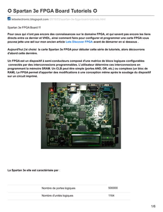
- 1. ✪ Spartan 3e FPGA Board Tutoriels ✪ letselectronic.blogspot.com /2016/03/spartan-3e-fpga-board-tutoriels.html Spartan 3e FPGA Board !!! Pour ceux qui n'ont pas encore des connaissances sur le domaine FPGA, et qui savent pas encore les liens directs entre ce dernier et VHDL, ainsi comment faire pour configurer et programmer une carte FPGA vous pouvez jette une œil sur mon ancien article Lets Discover FPGA avant de démarrer en si dessous . Aujourd'hui j'ai choisi la carte Spartan 3e FPGA pour débuter cette série de tutoriels, alors découvrons d'abord cette dernière. Un FPGA est un dispositif à semi-conducteurs composé d'une matrice de blocs logiques configurables connectés par des interconnexions programmables. L'utilisateur détermine ces interconnexions en programmant la mémoire SRAM. Un CLB peut être simple (portes AND, OR, etc.) ou complexe (un bloc de RAM). Le FPGA permet d'apporter des modifications à une conception même après le soudage du dispositif sur un circuit imprimé. La Spartan 3e elle est caractérisée par : Nombre de portes logiques 500000 Nombre d'unités logiques 1164 1/6
- 2. Nombre de registres 9312 Nombre de multiplieurs 20 (18 x 18) Type de montage CMS Type de boîtier FBGA Nombre de broche 320 Nombre de bits de RAM 74752 bit Dimensions 19 x 19 x 1.4mm Hauteur 1.4mm Longueur 19mm Tension d'alimentation fonctionnement maximum 1,26 V Température de fonctionnement minimum 0 °C Température d'utilisation maximum +85 °C Largeur 19mm Tension d'alimentation de fonctionnement minimum 1,14 V 2/6
- 3. Alors pour débuter avec Spartan 3e, on a choisi des test simples tels que contrôler les Diodes Led sur la carte. pour ceci comme j'ai déjà expliquer dans mon article précédant je doit utiliser ISE et programmer en VHDL. Voila le programme qui est capable de faire allumer tout les Led sur Spartan 3e. 3/6
- 4. // Hello Word !!d ---------------------------------------------------------------------------------- -- Company: -- Engineer: Aymen Lachkhem -- -- Create Date: 15:01:03 03/23/2016 -- Design Name: -- Module Name: Testing_LEDS - Behavioral -- Project Name: -- Target Devices: -- Tool versions: -- Description: -- -- Dependencies: -- -- Revision: -- Revision 0.01 - File Created -- Additional Comments: -- ---------------------------------------------------------------------------------- library IEEE; use IEEE.STD_LOGIC_1164.ALL; -- Uncomment the following library declaration if using -- arithmetic functions with Signed or Unsigned values --use IEEE.NUMERIC_STD.ALL; -- Uncomment the following library declaration if instantiating -- any Xilinx primitives in this code. --library UNISIM; --use UNISIM.VComponents.all; entity Testing_LEDS is Port ( LED_1 : out STD_LOGIC; LED_2 : out STD_LOGIC; LED_3 : out STD_LOGIC; LED_4 : out STD_LOGIC; LED_5 : out STD_LOGIC); end Testing_LEDS; architecture Behavioral of Testing_LEDS is begin LED_1 <= '1'; LED_2 <= '1'; LED_3 <= '1'; LED_4 <= '1'; LED_5 <= '1'; end Behavioral; et Pour la configurations des pins j'ai fait ça : NET "LED_1" LOC = "F12"; NET "LED_2" LOC = "E12"; NET "LED_3" LOC = "E11"; NET "LED_4" LOC = "F11"; NET "LED_5" LOC = "C11"; Voici cette vidéo vous expliquerez pas à pas tout les taches faites, et vous montrerez le test pratique. 4/6
- 5. On va passé maintenant dés d'allumer les leds a les faire controler chaque une par un switcheur inclus dans la carte Spartan 3e, au niveau du programme, il y aura pas beaucoup de changement il faut juste boucler l'allumage par des conditions répétitives de switcheurs. // Leds,Buttons Interfacing--------------------------------------------------------------- ------------------- -- Company: -- Engineer: -- -- Create Date: 17:13:12 03/23/2016 -- Design Name: -- Module Name: Button_LEDS - Behavioral -- Project Name: -- Target Devices: -- Tool versions: -- Description: -- -- Dependencies: -- -- Revision: -- Revision 0.01 - File Created -- Additional Comments: -- ---------------------------------------------------------------------------------- library IEEE; use IEEE.STD_LOGIC_1164.ALL; -- Uncomment the following library declaration if using -- arithmetic functions with Signed or Unsigned values --use IEEE.NUMERIC_STD.ALL; -- Uncomment the following library declaration if instantiating -- any Xilinx primitives in this code. --library UNISIM; --use UNISIM.VComponents.all; entity Button_LEDS is Port ( Button_1 : in STD_LOGIC; Button_2 : in STD_LOGIC; Button_3 : in STD_LOGIC; Button_4 : in STD_LOGIC; Led_1 : out STD_LOGIC; Led_2 : out STD_LOGIC; Led_3 : out STD_LOGIC; Led_4 : out STD_LOGIC); end Button_LEDS; architecture Behavioral of Button_LEDS is begin WORK:process begin if(Button_1 = '1') then Led_1 <= '1'; else Led_1 <= '0'; end if; if(Button_2 = '1') then Led_2 <= '1'; else Led_2 <= '0'; 5/6
- 6. Led_2 <= '0'; end if; if(Button_3 = '1') then Led_3 <= '1'; else Led_3 <= '0'; end if; if(Button_4 = '1') then Led_4 <= '1'; else Led_4 <= '0'; end if; end process; end Behavioral; et Pour la configurations des pins j'ai fait ça : NET "Button_1" LOC = "N17"; NET "Button_2" LOC = "L13"; NET "Button_3" LOC = "H18"; NET "Button_4" LOC = "L14"; NET "Led_1" LOC = "E9"; NET "Led_2" LOC = "F12"; NET "Led_3" LOC = "E11"; NET "Led_4" LOC = "C11"; Voici cette vidéo vous expliquerez pas à pas tout les taches faites, et vous montrerez le test pratique. 6/6